Page 485 - Tar River Updated
P. 485
Optional Safety Light Assembly          PARTS CATALOG
         BCP3616

         Always  comply  with  all  state  and  local
         laws  governing  highway  safety  and
         lighting and marking requirements.                    lamps, module, and pig tail.

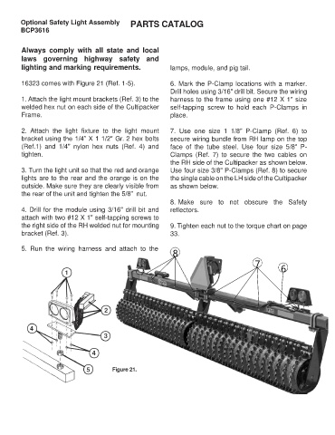
         16323 comes with Figure 21 (Ref. 1-5).                6. Mark the P-Clamp locations with a marker.
                                                               Drill holes using 3/16" drill bit. Secure the wiring
         1. Attach the light mount brackets (Ref. 3) to the    harness to the frame using one #12 X 1" size
         welded hex nut on each side of the Cultipacker        self-tapping  screw  to  hold  each  P-Clamps  in
         Frame.                                                place.

         2.  Attach  the  light  fixture  to  the  light  mount   7.  Use  one  size  1  1/8"  P-Clamp  (Ref.  6)  to
         bracket using the 1/4” X 1 1/2" Gr. 2 hex bolts       secure wiring bundle from RH lamp on the top
         (Ref.1)  and  1/4"  nylon  hex  nuts  (Ref.  4)  and   face  of  the  tube  steel.  Use  four  size  5/8"  P-
         tighten.                                              Clamps  (Ref.  7)  to  secure  the  two  cables  on
                                                               the RH side of the Cultipacker as shown below.
         3. Turn the light unit so that the red and orange     Use four size 3/8" P-Clamps (Ref. 8) to secure
         lights are to the rear and the orange is on the       the single cable on the LH side of the Cultipacker
         outside. Make sure they are clearly visible from      as shown below.
         the rear of the unit and tighten the 5/8”  nut.
                                                               8. Make  sure  to  not  obscure  the  Safety
         4. Drill for the module using 3/16" drill bit and     reflectors.
         attach with two #12 X 1" self-tapping screws to
         the right side of the RH welded nut for mounting      9. Tighten each nut to the torque chart on page
         bracket (Ref. 3).                                     33.


         5.  Run  the  wiring  harness  and  attach  to  the
                                                                8
                                                                                              7         6


                                          Figure 21.

