
Page 25 - 233423 - Exhaust Fans_Neat
P. 25
INSTALLATION
When the unit is installed on a sloped roof, suitable footing and/or other safety devices must be provided around
the ventilator for normal maintenance. Depending upon the site conditions, the hinging of the ventilator off the curb
CAUTION during maintenance should be either parallel to the roof ridge or toward the roof ridge but NOT away from the ridge.
NFPA-96 recommends that dampers should not be installed when exhauster is used for the removal of smoke and
grease laden vapors from commercial cooking equipment. Consult state and local codes for detailed requirements.
CAUTION
For installation in high velocity hurricane zones, unit must be installed per instructions under Anchoring and Installing
the Ventilator
CAUTION
To fulfill our obligations towards Article 33, in accordance to European REACH Regulation No 1907/2006 EC, we hereby
inform you that this article contains the following Substances of Very High Concern mentioned on the Candidate list:
WARNING
• Lead
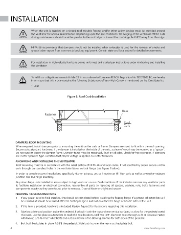
Figure 1: Roof Curb Installation
Base
Fastener
Roof
Curb
DAMPERS: ROOF MOUNTING
When required, install dampers prior to mounting the unit on the curb or frame. Dampers are sized to fit within the roof opening.
Secure using standard hardware. If the damper is installed on the inside of the curb, a piece of wood may be required as a “spacer”.
Do not twist or distort the damper frame. Damper frame must be reasonably level on all sides. Check for free operation. If dampers
are motor operated type, ascertain that proper voltage is applied on motor terminals.
ANCHORING AND INSTALLING THE VENTILATOR
Roof mounting must be in accordance with the latest edition of NFPA-96 and local codes. If not specified by codes, secure unit to
curb through pre-punched holes in the ventilator base’s vertical flange (see Figure 1 below).
In order to complete some installations, specifically kitchen exhaust, you will require an 18” high curb as well as a weather resistant
junction box and hinge assembly.
Guy down large units installed in areas subject to high winds or unusual field conditions. If the installer removes any ventilator parts
to facilitate installation or electrical connection, reassemble all parts by replacing all spacers, washers, nuts, bolts, fasteners and
components exactly as they were found prior to removal. Draw all fasteners tight and secure.
FLOATING HINGE INSTRUCTIONS
1. If any gasket is to be field installed, this should be completed before installing the floating hinge. If a grease collection box will
be installed, it should be installed after the floating hinge is and not on either the hinge or handle sides of the unit.
2. If this item is provided, hardware is included. Review figure 2 for illustrations regarding this installation.
3. Take backplate and position inside the pedestal, flush with both the top and rear vertical surfaces, to allow for the pedestal metal
thickness. Use this plate as a template to mark the hole locations. Drill two “3/8” diameter holes through curb or pedestal. Fasten
with two (2) 3/8-16 X 1/2” whiz bolts and nuts as shown in the drawing. Do this for both sides of the pedestal.
4. Bolt both backplates in place INSIDE the pedestal. Slide bushing over the rear most backplate bolt.
4 www.PennBarry.com