
Page 26 - 233423 - Exhaust Fans_Neat
P. 26
INSTALLATION
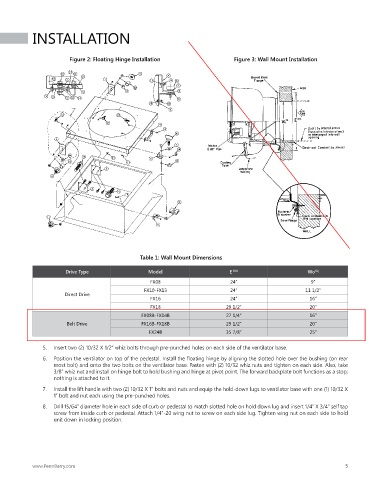
Figure 2: Floating Hinge Installation Figure 3: Wall Mount Installation
Table 1: Wall Mount Dimensions
Drive Type Model E DIA Wo SQ
FX08 24” 9”
FX10-FX13 24” 11 1/2”
Direct Drive
FX16 24” 16”
FX18 29 1/2” 20”
FX08B-FX14B 27 1/4” 16”
Belt Drive FX16B-FX18B 29 1/2” 20”
FX24B 35 7/8” 25”
5. Insert two (2) 10/32 X 1/2” whiz bolts through pre-punched holes on each side of the ventilator base.
6. Position the ventilator on top of the pedestal. Install the floating hinge by aligning the slotted hole over the bushing (on rear
most bolt) and onto the two bolts on the ventilator base. Fasten with (2) 10/32 whiz nuts and tighten on each side. Also, take
3/8” whiz nut and install on hinge bolt to hold bushing and hinge at pivot point. The forward backplate bolt functions as a stop;
nothing is attached to it.
7. Install the lift handle with two (2) 10/32 X 1” bolts and nuts and equip the hold-down lugs to ventilator base with one (1) 10/32 X
1” bolt and nut each using the pre-punched holes.
8. Drill 15/64” diameter hole in each side of curb or pedestal to match slotted hole on hold down lug and insert 1/4” X 3/4” self tap
screw from inside curb or pedestal. Attach 1/4”-20 wing nut to screw on each side lug. Tighten wing nut on each side to hold
unit down in locking position.
www.PennBarry.com 5