
Page 72 - 233423 - Exhaust Fans_Neat
P. 72
Operation & Maintenance Manual Zephyrette & Zephyr Jr. Ceiling Exhaust Ventilators
5. Make certain the power source con- BEFORE A CEILING IS INSTALLED 6. Complete installation by cutting
forms to the requirements shown in WITH ACCESS FROM BELOW an 11-7/8" x 13-3/4" ceiling opening
the performance chart. for the unit. Use care not to
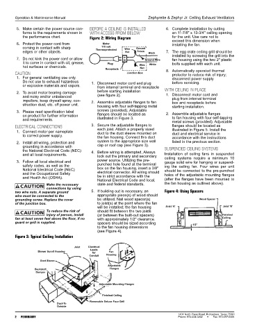
Figure 2: Wiring Diagram exceed this dimension when
6. Protect the power cord from Motor installing the fan.
115 volt
coming in contact with sharp Thermoprotected Wire Ground
edges or other objects. Nut Screw Black 7. The egg crate ceiling grill should be
installed by screwing the grill into the
7. Do not kink the power cord or allow Ground Wire fan housing using the two 2" plastic
it to come in contact with oil, grease, Plug White bolts supplied with each unit.
hot surfaces or chemicals. Wire
Receptacle Nut 8. Automatically operated thermal
CAUTION Junction Box protector to reduce risk of injury;
1. For general ventilating use only. disconnect power supply
Do not use to exhaust hazardous 1. Disconnect motor cord and plug before servicing.
or explosive materials and vapors. from internal terminal and receptacle
2. To avoid motor bearing damage before starting installation WITH CEILING IN PLACE
1. Disconnect motor cord and
and noisy and/or unbalanced (see figure 2).
impellers, keep drywall spray, con- 2. Assemble adjustable flanges to fan plug from internal terminal
box and receptacle before
struction dust, etc. off power unit. housing with four self-tapping metal starting installation.
3. Please read specification label screws (provided). Adjustable 2. Assemble adjustable flanges
on product for further information flanges should be located as
and requirements. illustrated in Figure 3. to fan housing with four self-tapping
metal screws (provided). Adjustable
ELECTRICAL CONNECTIONS 3. Secure the adjustable flanges to flanges should be located as
each joist. Attach a properly sized
1. Connect motor per nameplate duct to the duct sleeve mounted on illustrated in Figure 5. Install the
to correct power supply. the fan housing. Connect this duct duct and electrical service in
accordance with the instructions
2. Install all wiring, protection and system to the appropriate size wall listed in the previous section.
grounding in accordance with cap or roof cap (see Figure 3).
the National Electrical Code (NEC) 4. Before wiring is attempted, Always SUSPENDED CEILING SYSTEMS
and all local requirements. lock out the primary and secondary Installation of ceiling fans in suspended
3. Follow all local electrical and power source. Utilizing the pre- ceiling systems require a minimum 10
gauge solid wire for hanging or suspend-
safety codes, as well as the punched hole found at the terminal ing the ceiling fan. Four wires per unit
National Electrical Code (NEC) box on the fan housing, insert a 3/8" should be connected to the pre-punched
and the Occupational Safety electrical connector. All wiring should holes of the adjustable mounting flanges
and Health Act (OSHA). be in strict accordance with the
National Electrical Code and local, (after the flanges have been mounted to
Make the necessary state and federal standards. the fan housing as outlined above).
connections by using
two wire nuts. A separate ground 5. If building out is necessary, an Figure 4: Using Spacers
wire must be connected to the appropriate piece(s) of wood should
grounding screw. Replace the cover be utilized. Nail wood spacer(s) Wood Spacer
of the junction box. to joist(s) at the point where the fan
will be installed; the fan housing Joist ‘A’ Joist ‘B’
To reduce the risk of should fit between the two joists
injury of person, install (or between the built-out spacers) Finished
fan at least seven feet above the floor, if no with approximately 1/2" clearance. Ceiling
guard or grill is supplied. spacers should be sized according 1/2"
to the fan housing dimensions
(see Figure 4).
Figure 3: Typical Ceiling Installation
Joist Electrical
Leads
Blower Scroll Housing Fan
for
Conduit Housing
Duct Sleeve
Adjustable
Backdraft Flanges
Damper
Adjustable Mounting Flanges
Finished Ceiling
Removable Deluxe Face Grill
Duct-To
Outside
1401 North Plano Road, Richardson, Texas 75081
2 PENNBARRY Phone: 972-234-3202 Fax: 972-497-0468