
Page 28 - Prosig Catalogue 2005
P. 28
HARDWARE PRODUCTS
WHAT IS THE DIFFERENCE BETWEEN SINGLE-ENDED & DIFFERENTIAL?
Bees wax or petroleum wax is not widely used, but if it is used then is amplified to the output. In
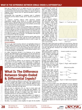
the temperature must be less than 20 deg C. However, wax adhesive is Figure 1 consider that the sine
sometimes preferred for hammer impact testing or in general Frequency wave was actually carried on
two copper wires. One would be
Response Function testing when the response transducer needs to be
Training & Support Cyanoacrylate glue (super-glue) is sometimes used in calibration AC (alternating current) signal Figure 1: +/- 5 volt sine wave
connected to earth or ground
moved frequently.
and the other would carry the
laboratories, but this method is rarely used for mounting transducers on
as seen in Figure 1.
vehicles.
There are however problems
For transducer mounting positions which experience elevated
with this method of cabling
temperatures (typically under vehicles or in engine compartments)
and transporting signals. The
dental cement is used especially when performing (hot) tests on running
main problem is that ground
vehicles. Mounting blocks are often used to keep adhesive cement away
from the threaded holes of the transducer.
in reality, at different levels
Mounting transducers on vehicle steering wheels presents a different sort
in different places. The closer
of problem which is the need to avoid marking or destroying the steering is not a constant 0V, but is,
these places are together then
wheel. One solution is to wrap duct tape around the steering wheel rim at the more likely the ground
the desired position and then use a clamp such as a hose clamp to grip a
Condition Monitoring be stud mounted to the mounting block. a connection between two Figure 2: Sine wave amplified by
levels will be the same. This is
mounting block to the rim. If desired the mounting block can be attached
often the main cause of errors
to the clamp by adhesive such as hot glue. The transducer itself may then
with single ended inputs. With
quite different grounds, the
Magnetically mounted transducers are sometimes used for quick vehicle
setup. This technique is not widely used, but can be useful if the test
difference in these levels can
cause large currents to flow,
engineer can find a suitable magnetic flat surface to which to attach the
these are commonly known as
mounting magnet.
factor of 2
earth or ground loops.
Recommendations
There is no one “best” mounting method for all applications because of
be injected into signals because the wire that carries the signals can act
the many different structural and environmental considerations, such as
as an aerial and thus pick up all manner of electrical background noise.
temporary or permanent mount, temperature, type of surface finish, and Additionally, single ended inputs can suffer from noise injection. Noise can
so forth. Almost any of the mounting methods described earlier when Once this noise has been introduced into the signal this way there is no
used at low acceleration levels provides the full frequency range of use if way to remove it.
the mounting surface is reasonably flat. Unlike single ended amplifiers,
As surface irregularities increase or the thickness of the adhesive differential amplifiers amplify the
voltage difference between two
Software adhesives reduce an accelerometer’s usable frequency range much more inputs. A single ended amplifier
increases, the usable frequency range decreases. The less-stiff, temporary
is shown in Figure 3 and a
than the more rigid, harder adhesives. Nevertheless, temporary adhesives
differential amplifier in Figure 4.
are quite satisfactory for low-frequency (<1000 Hz) structural testing at
room temperatures.
powered in the same way, but
When using adhesives, problems can be expected at high frequencies Both these types of amplifier are
in proportion to the size of mass of the accelerometer. If possible, an the differential amplifier, amplifies
accelerometer should be calibrated using a back-to-back accelerometer the difference between its two Figure 3: Single ended amplifier
system using exactly the same mounting method that will be used in inputs, whereas the single ended
the actual test. In this manner, the precise behavior of the measurement amplifier, amplifies the difference
system can be determined at the expected frequencies. between its single input and
ground.
The differential signal, and the
What Is The Difference
cabling method used, eliminates
Hardware Between Single-Ended common mode noise. This is
unwanted noise that is injected
into both wires, but because only
the difference between the inputs
& Differential Inputs?
is measured it is ignored. This
without
increasing
unwanted
Prosig P8000 systems use differential inputs, but what are they and why allows for much longer cables Figure 4: Differential amplifier
are they so special? This subject is not always fully understood and, noise in the measured signal.
therefore, the focus of this article is to try to make the difference clearer However, a common problem when using differential inputs is neglecting
and explain why differential inputs are the obvious choice in a high quality, any possible connection to ground. For example, in the case of battery
System Packages differential inputs. To that end we should start with amplifiers. The Furthermore, when you consider all three of these voltages, ground,
powered equipment, the battery and circuits might produce signals that
high precision system like the Prosig P8000.
are near the limit of the amplifier. If a ground is introduced into the circuit
First, we need to understand what we mean by single ended and
the levels could be significantly different to that of the battery voltages.
difference between single ended and differential ended inputs is the
battery – and battery +, the levels could be outside the operational range
difference between the types of amplifiers used. Most modern data
of the amplifier. These situations are known commonly as floating signals.
acquisition systems will have some sort of signal amplifiers.
The signals are not referenced to ground. In these cases it is required
Amplifiers will, quite simply, take a signal and amplify it. For example, in
to introduce a ground to provide this reference. For this situation the
Figure 1 we have a sine wave with an amplitude of +/-5 Volts. If this were
instrumentation, in this case a Prosig P8000, has a GND connection. A
amplified by a factor of two, the result would be as shown in Figure 2 - a
wire would be inserted here and connected to the electrical ground. Thus
sine wave with an amplitude of +/- 10Volts.
the differential signals are measured against each other with reference
28 Therefore, if we consider a simple amplifier, the signal into the amplifier to ground.
+1 248 443 2470 (USA)
or contact your
http://prosig.com
+44 (0)1329 239925 (UK) local representative
sales@prosig.com
A CMG Company