
Page 25 - Prosig Catalogue 2005
P. 25
HARDWARE PRODUCTS
ACCELEROMETER MOUNTING METHODS
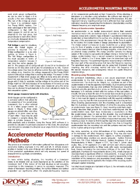
used strain gauge configuration. of the measurement particularly at high frequencies. When attaching a
As can be seen in Figure 5 it is transducer to a structure using adhesives, the stiffness and strength of
actually a five wire configuration. the glue will affect the usable frequency range of the transducer. It is also
The rest of the bridge as shown important that any mounting method that is different from that used for
in Figure 2 is completed inside calibration should be characterized for its dynamic characteristics over the
the Prosig P8000 system. The intended frequency and amplitude range.
main advantage of the Half Bridge Theory of Accelerometer Operation
configuration is that both the
strain gauges S1 and S2 can be An accelerometer is an inertial measurement device that converts
attached to the test piece, but Figure 5: Half bridge mechanical motion into an electrical signal. It consists of a piezoelectric Training & Support
perpendicular to each other. Which (quartz) crystal and a seismic mass enclosed in a protective metal case.
as previously discussed allows for Acceleration is transmitted from the surface of a vibrating structure into
temperature compensation. the case of the accelerometer through the base. As the force is applied
to the crystal, the crystal creates a charge proportional to acceleration.
Full bridge is used for situations The charge output is measured in pico Coulombs per g (pC/g) where
2
where the fullest degree of g is the force of gravity, or pico Coulombs per metres/second (pC/m/
2
accuracy is required. The Full sec ). Some sensors have an internal charge amplifier, while others have
Bridge configuration is a six wire an external charge amplifier. The charge amplifier converts the charge
2
system, as shown in Figure 6. output of the crystal to a proportional voltage (mV/g or mV/m/sec ). By
The Full Bridge configuration is design, accelerometers have a natural resonance (corresponding to f
n
the most accurate in terms of in figure 1) which is 3 to 5 times higher than the advertised high end
temperature variation because it Figure 6: Full bridge frequency response. The operating frequency response range is limited to
can have two active gauges, S1 the lower part of the operating range that has a flat frequency response.
and S4. The gauges can be configured with S1 and S4 in the direction of The advertised range is achievable only by using bolt (threaded stud) Condition Monitoring
interest on the test piece and S2 and S3 perpendicular to this. Further mounting. Any other mounting method will lower the frequency of
the voltage sense lines have no effective current flow and therefore have the natural resonance, and consequently reduce the usable frequency
no voltage drop, therefore the voltage measured by the Prosig P8000 response range.
system is the actual voltage that is exciting the bridge. The reason for this Mounting using Threaded Studs
requirement is that strain gauges are often on long wires and all wires For permanent installations, where a very secure attachment of the
have their own resistance. The Prosig P8000 system could be exciting the accelerometer to the test structure is preferred, stud mounting is
gauge with 5 Volts for example, but the voltage at the active part of the recommended. The stud may be integral, i.e., machined as part of the
bridge might be 4.95 Volts because of the resistance of the wires carrying accelerometer or it may be separate (removable). Stud mounting provides
the supply voltage. This small change once measured using the sense higher transmissibility than any other method. The transducer should be
lines can be allowed for automatically in the strain calculations inside the mounted using the specified stud or screw, so that the entire base of the
data acquisition system.
transducer is in intimate contact with the surface of the test article. A
Strain gauge measurements with direction. smooth, flat area at least the size of the sensor base should be ground or
machined on the test object according to the manufacturer’s specifications. Software
Strain Gauges can be configured in Then a hole must be tapped in accordance with the supplied installation
a particular pattern that allows for drawing, ensuring that the hole is perpendicular to the mounting surface.
the calculation of the overall strain When installing accelerometers with the mounting stud it is important
component, this is often referred that the stud does not reach the bottom of either the mounting surface
to as a strain gauge rosette. As or accelerometer base (see figure 2). Good mounting studs have depth-
shown in Figure 7, three strain limiting shoulders that prevent the stud from bottoming-out into the
gauges are placed either very close accelerometer’s base. Each base incorporates a counterbore so that
together or in some cases on top the accelerometer does not rest on the shoulder. Any stud bottoming
of each other. These may be used or interfering between the accelerometer base and the structure will
to measure a complex strain, the Figure 7: Strain gauge rosette inhibit acceleration transmission and affect measurement accuracy. When
strain is complex because it has installing a stud, it is best to first thread the stud into the accelerometer
both amplitude and a direction. Using the Prosig DATS software it is to ensure that the stud fully enters the threaded hole, then to thread the
possible to calculate the principal component of the strain, the amplitude accelerometer into the mounting hole until the surfaces meet and finally
over time and to calculate the direction as an angle from the reference X screw in place using a torque wrench. Hardware
axis over time.
Any nicks, scratches, or other deformations of the mounting surface
or the transducer will affect frequency response. They may also result
Accelerometer Mounting in damage to the accelerometer. With regards to surface preparation,
Methods good machine-shop practices are usually adequate - Surface Flatness
0.076 mm TIR (Total Indicator Runout), Surface Roughness 0.8 μm,
This article is an overview of information gathered from discussions with Perpendicularity of Hole: 1 degree ± 0.5°, Tap Class 2. (when using
studs). Also, a thin application of a light lubricant such silicone grease
automotive testing engineers in the USA and UK. It reflects modern will improve transmissibility by filling voids with nearly incompressible
practice in testing in the area of design and refinement and also in end- fluid, thereby increasing the compressive stiffness of the joint. This is
of-line production applications where not only accuracy but speed of particularly important for measurements above 2 kHz, where changes in
measurement is a primary consideration. resonance have a significant effect on measurements. A torque wrench
Introduction should be used to mount all accelerometers ensuring repeatability in the
In many vehicle testing situations, the mounting of a transducer installation of the transducers and preventing thread damage. A thread- System Packages
locking compound may be applied to the threads of the mounting stud to
needs to be treated with as much importance as the selection of the safeguard against loosening.
transducer itself. If the motion of the test structure is not accurately
transmitted to the transducer, it cannot be accurately measured. The Two stud mount designs are illustrated in figure 3, the removable stud (a)
choice of transducer mounting method, the surface flatness and surface and the integral stud (b).
preparation can significantly affect the amplitude-frequency response
http://prosig.com +1 248 443 2470 (USA) or contact your 25
sales@prosig.com +44 (0)1329 239925 (UK) local representative
A CMG Company