
Page 24 - Prosig Catalogue 2005
P. 24
HARDWARE PRODUCTS
STRAIN GAUGES EXPLAINED
Resistivity is provided by the manufacturer of the material in question hence, a strain value.
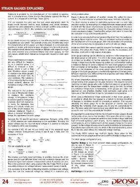
and is a measurement of how strongly the material opposes the flow of Figure 3 shows the addition of another resistor RS, called the shunt
current. It is measured in ohm’s per meter (Ω/m). resistor. The shunt resistor is a known fixed value, normally 126,000Ω.
Training & Support Suppose the cable extended to 2 meters in length and the cross sectional A and B with the known shunt resistor across Rx and also with the shunt
The Shunt resistor is added for calibration purposes and is a very high
If in our example the cable was then put under appropriate strain its
precision resistor. By measuring the voltage between measurement points
length would increase and its cross sectional area would decrease.
resistor removed it is possible to relate the measured voltage change to a
area decreased to 0.5mm , the resistance now would be
2
known resistance change. Therefore the volt per ohm value is known for
-8
1.8x10 x 2
0.000000018
this particular bridge and this particular Rx.
0.072Ω
R =
=
=
0.005
0.00000025
2
In order to go one step further and calculate the strain from the resistance,
the gauge factor must be known. This is a calibrated number provided by
As can clearly be seen the resistance is now different, but the resistances
in question are very small. This example shows only the difference when
of the whole sensor may be calculated in terms of volts per strain.
the characteristics of the copper wire have changed. It is not practically
possible to stretch and extend a piece of copper wire by such amounts. the manufacturer of the strain gauge. With this information the sensitivity
Inside the P8000 the resistors used to complete the bridge are very high
The example merely shows how resistance changes with respect to length precision. This allows the Prosig P8000 to calculate the resistance, and
and cross sectional area and demonstrates that strain gauges, by their therefore, strain with a high degree of accuracy.
Condition Monitoring These small resistance changes or contract as an effect of thermal expansion. This will be detected as a
very nature, exhibit small resistance changes with respect to strain upon
Strain gauge readings can be affected by variations in the temperature of
them.
the strain gauge or test piece. The wire in the strain gauge will expand
are very difficult to measure.
change in strain levels by the measuring system as it will manifest itself as
So, in a practical sense, it is
a resistance change. In order to address this most strain gauges are made
difficult to measure a strain
from Constantan or Karma alloys. These are designed so that temperature
gauge, which is just a long
effects on the resistance of the strain gauge cancel out the resistance
wire. Whatever device is used
change of the strain gauge due to the thermal expansion of the test piece.
to measure the strain gauge’s
resistance will itself have its
amounts of thermal expansion.
own resistance. The resistance
So, where temperature change during the test is an issue, temperature
of the measuring device would Different materials have different thermal properties and hence differing
almost certainly obscure the compensating strain gauges can be used. However this requires correctly
resistance change of the strain Figure 2: A Wheatstone bridge matching the strain gauge alloy with the thermal expansion properties of
gauge. the test piece and the temperature variation during the test. In certain
circumstances temperature compensating strain gauges are either not
Software is to use a Wheatstone bridge make use of the Wheatstone bridge for temperature compensation.
The solution to this problem
practical nor cost effective. Another more commonly used option is to
to measure the resistance
When using a Wheatstone bridge constructed of four strain gauges, it
change. A Wheatstone bridge
is possible to attach the four gauges in a fashion to remove the effect
is a device used to measure an
unknown electrical resistance.
attaching the strain gauge Rx in the direction of interest and then
It works by balancing two of changes in resistance caused by temperature variation. This requires
halves of a circuit, where one attaching the remaining strain gauges, R2, R3 and R4, perpendicular to
half of the circuit includes the this. The piece under test however must only exhibit strain in the direction
unknown resistance. Figure 2 Figure 3: With shunt resistor across Rx and not in the perpendicular direction.
shows a classical Wheatstone It’s important to understand that the R2, R3 and R4 strain gauges should
bridge, Rx represents the strain gauge. not be under strain, hence their direction. This means the whole bridge is
Resistors R2, R3 and R4 are known resistances. Typically, 120Ω, 350Ω subject to the same temperature variations and therefore stays balanced
from a thermal expansion point of view. As the resistance changes due
Hardware supply voltage and the returned signal voltage it is possible to calculate amount. So the voltage at measurement points A and B due to temperature
or 1000Ω resistors are used depending on the application. Knowing the
to temperature, all the resistances in all four gauges change by the same
the resistance of Rx very accurately.
fluctuations stays constant. Only the strain in the desired direction, across
For example if R2, R3 and R4 are 1000Ω and if the measured signal
Rx, in the test piece affects the measured voltage readings.
voltage between measurement points A and B was 0 Volts then the
The Prosig P8000 system has multi-pin inputs, these allow for the
resistance of Rx is
connection of strain gauges in all the various different bridge configurations.
R3 Rx R3
= or Rx = x R2 The strain gauge configurations are,
R2
R4 1000Ω R4 Quarter Bridge is the most common strain gauge configuration. As
can be seen in Figure 4
For our example we get
System Packages This implies a perfectly balanced bridge. In practice, because the strain of the bridge as shown
it is actually a three wire
configuration. The rest
=
=
x 1000Ω
1000Ω
Rx
1000Ω
in Figure 2 is completed
inside the Prosig P8000
system. Quarter Bridge
gauge goes through different strain levels its resistance changes and the
uses three wires to allow
measured signal level between measurement points A and B is not zero.
for accurate measurement
This is not a problem when using a system like the Prosig P8000 as it can
of the actual voltage
accurately measure the voltage between measurement points A and B.
across S1.
It is necessary to know the relationship between resistance and voltage.
24 Only then can the measured voltage be related to a resistance and, Half Bridge is not an often Figure 4: Quarter bridge
or contact your
+1 248 443 2470 (USA)
http://prosig.com
sales@prosig.com
+44 (0)1329 239925 (UK) local representative
A CMG Company