
Page 21 - Prosig Catalogue 2005
P. 21
HARDWARE PRODUCTS
STRAIN GAUGES EXPLAINED
more electronics in the system the more noise imposed by the system. ±10V then the smallest voltage that the system can distinguish will be:
In data acquisition and signal processing the noise floor is a measure of 20 / 65536 = 0.3 mV
In decibels this dynamic range is therefore expressed as:
20 Log (1 / 65536) = 96dB
10
Therefore for a 16-bit ADC the dynamic range is 96dB. Using the same
calculations the dynamic range of a 24-bit ADC is 144dB.
The noise floor of a measurement system is also limited by the resolution Training & Support
of the ADC system. For example, the noise floor of a 16-bit measurement
system can never be better than -96dB and for a 24-bit system the lower
limit is limited to -144 dB. In practice, however, the noise floor will always
be higher than this due to electronic noise within the measurement
system.
Modern data acquisition systems, such as the Prosig P8000, employ a
number of sophisticated digital signal processing techniques to improve
the amplitude resolution and thereby allow low amplitude data, such
as noise floor signals, to be measured with greater precision and with
greater accuracy.
Strain Gauges Explained Condition Monitoring
Figure 2
A strain gauge is an electrical sensor which is used to accurately measure
the summation of all the noise sources and unwanted signals generated strain in a test piece. Strain gauges are usually based on a metallic foil
within the entire data acquisition and signal processing system. The noise pattern. The gauge is attached to the test piece with a special adhesive.
floor limits the smallest measurement that can be taken with certainty As the test piece is deformed, so the adhesive deforms equally and thus
since any measured amplitude cannot on average be less than the noise the strain gauge deforms at the same rate and amount as the test piece.
floor. It is for this reason that the adhesive must be carefully chosen. If the
adhesive cracks or becomes detached from the test piece any test results
In summary, the noise floor is the level of background noise in a signal, or
the level of noise introduced by the system, below which the signal being will be useless.
captured cannot be isolated from the noise. Strain gauges are used not just for metals; they have been connected to
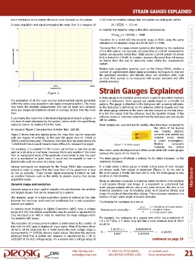
As shown in Figure 1 the noise floor is better than -120 dB. the retina of the human
eye, insects, plastics,
Figure 2 shows that only signals above the noise floor can be measured concrete and indeed any Software
with any degree of certainty. In this case the signal level of -100dB at material where strain
20KHz could be measured. If however, the noise floor increased above the is under investigation.
-120dB level then it would become more difficult to measure this signal. Figure 1: A strain gauge Modern composite
materials like carbon
For example, it is possible for the human ear to hear a very low sound fibre when under development are often constructed with strain gauges
such as a pin drop or a whisper. However, this is only possible if the noise between the layers of the material.
floor or background noise of the particular environment is very low such
as in a soundproof or quiet room. It would not be possible to hear or The strain gauge is effectively a resistor. As the strain increases so the
discriminate such low levels in a noisy room. resistance increases.
Various techniques are employed by the Prosig P8000 data acquisition In a basic sense a strain gauge is simply a long piece of wire. Gauges
system in order to ensure that the noise floor of the equipment is kept are mostly made from copper or aluminium (Figure 1). As the wire in
as low as possible. These include signal-processing functions as well the strain gauge is mostly laid from end to end, the strain gauge is only
as practical features such as the ability to disable cooling fans during sensitive in that direction. Hardware
acquisition scans.
When an electrical conductor is stretched within the limits of its elasticity
Dynamic range and resolution it will become thinner and longer. It is important to understand that
strain gauges actually deform only a very small amount, the wire is not
Dynamic range is a term used to describe the ratio between the smallest stretched anywhere near its breaking point. As it becomes thinner and
and largest signals that can be measured by a system. longer it’s electrical characteristics change. This is because resistance is a
The dynamic range of a data acquisition system is defined as the ratio function of both cable length and cable diameter.
between the minimum and maximum amplitudes that a data acquisition The formula for resistance in a wire is
system can capture.
ρ x L ρ = Resistivity (ohms per meter)
In practice most Analogue to Digital Converters (ADC) have a voltage Resistance in ohms (R) = L = length in meters
range of ± 10V. Sometimes amplification may be applied to signals before α α = cross section (m )
2
they are input to an ADC in order to maximize the input voltages within
the available ADC range. For example, the resistance of a copper wire which has a resistivity of
1.8 x 10 Ω/m, is 1 meter long and has a cross sectional area of 2mm System Packages
-8
2
The resolution of a measurement system is determined by the number of would be
bits that the ADC uses to digitise an input signal. Most ADCs have either
-8
16-bit or 24-bit resolution. For a 16-bit device the total voltage range is 1.8x10 x 1 0.000000018
16
represented by 2 (65536) discrete digital values. Therefore the absolute R = 0.002 2 = 0.000004 = 0.0045Ω
minimum level that a system can measure is represented by 1 bit or
1/65536 of the ADC voltage range. For a system with a voltage range of continued on page 24
th
http://prosig.com +1 248 443 2470 (USA) or contact your 21
sales@prosig.com +44 (0)1329 239925 (UK) local representative
A CMG Company