
Page 74 - Prosig Catalogue 2005
P. 74
CONDITION MONITORING
MEASURING SHAFT DISPLACEMENT
time mimic diagrams, trend displays, vector diagrams, alert
Measuring Shaft Displacement
processing and also for historical analysis.
Shaft displacement is an important vibration measurement Transducer Orientation
Training & Support as eddy-current probes. These probes produce a voltage displacement probes are often used to allow measurement
for rotating machines. Shaft displacement is usually
monitored by non-contact shaft displacement probes such To be of most benefit a pair of perpendicular shaft
proportional to the distance of the shaft surface relative to of the movement in both the vertical and horizontal
the tip of the probe. For maximum benefit, ideally two shaft directions.
probes
displacement
NOTE: It is often not physically possible to mount probes
will be fitted to measure
the displacement in
system configuration allows the actual transducer mounting
both the horizontal and
position to be defined. It can then mathematically combine
vertical directions. in the actual vertical and horizontal planes. The PROTOR
the contributions of a pair of probes to estimate the actual
The diagram opposite displacement in the true vertical and horizontal planes.
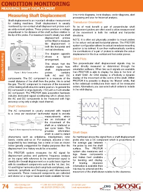
Condition Monitoring Figure 1: Eddy Current probes arrangement. contains Two perpendicular shaft displacement signals may be
shows
typical
a
Orbit Plots
This shows that the
either directly measured or determined through the
vibration signal from
orientation software. When two such signals are available
displacement
shaft
then PROTOR is able to display the data in the form of
probes
and
AC
both
DC
display of the movement of the centre of the shaft. Within
components. The DC component is a measure of the
PROTOR it is possible to display the ‘filtered’ orbits, that
overall distance of the shaft from the probe, this is called a shaft ‘Orbit’. An Orbit display is effectively a dynamic
the gap. The AC component is measure of the movement is the individual contributions from each of the measured
of the rotating shaft about its central position. In general the orders. Alternatively you can select which orders to include
DC component is large (typically -15V) with a much smaller in the orbit display.
AC component. The PROTOR data acquisition hardware
Software includes dedicated signal conditioning which allows both
the AC and DC components to be measured with high
accuracy using only a single input channel.
Shaft Vibration
The AC component is usually analyzed with respect
to a ‘once per revolution’ tachometer signal to provide
measurements which
are an indication of
the movement of the
Hardware Figure 2: Rotor supported by two bearings ‘per cycle’ basis. This Shaft Gaps
shaft on a rotational or
information
provides
which is used to detect
phenomena such as unbalance, misalignment, rotor As mentioned above the signal from a shaft displacement
bends, cracks and so on. For example, assume a rotor, probe also has a DC component which is proportional to
supported by two bearings, has a bend or bow as shown the average gap between
below (greatly exaggerated for display purposes then the the probe tip and the shaft
displacement time history would be sinusoidal. surface. The components
PROTOR
System Packages displacement probes and performs frequency analysis and makes them available
system also measures and
The PROTOR system measures the AC signal for
these
logs
on the signal with reference to the tachometer signal to
for trending and display.
identify the Overall displacement on a cyclic basis together
If
bearing
clearance
with its constituent components such as the 1st, 2nd, 3rd,
information is available then
4th and higher harmonics (both amplitude and phase), sub-
this may be entered and the
harmonic (amplitude and frequency) and intra-harmonic
movement of the shaft shown relative to the clearance.
components. These measured components are collected
74 and stored on a regular basis and made available for real-
http://prosig.com
or contact your
+1 248 443 2470 (USA)
sales@prosig.com
+44 (0)1329 239925 (UK) local representative
A CMG Company