
Page 312 - Divyank Tyagi
P. 312
278 | ChAPter 8 AdvAnced Modeling And MAssing
You’ve already started the command with either the Model In-Place or In-Place Mass
command. The next step will be to create the 3D geometry inside the family. Mass geometry is
created in a two-step process: First, create the 2D shape of the object; then use the Create Form
tool to generate the 3D geometry. This process is different from typical modeling software
applications because it does not require you to choose a specific modeling command before you
begin to explore your design.
Now, let’s get into the details with the following steps:
1. For the cube, you’ll first need to sketch a square in a plan view. From the Create tab
in the ribbon, in the Draw panel, use the Line or Rectangle tool to sketch a 100’ × 100’
(30 m × 30 m) square.
2. Activate the default 3D view, and then click the Modify button in the ribbon. Select the
lines you sketched in the previous step. You may need to press the Tab key to ensure that
all four lines of the square are selected. From the contextual tab in the ribbon, choose
the Create Form fly-out tool from the Form panel, and choose Solid Form. You will see
a dimension in the 3D view that indicates the default height of the extrusion. Click the
dimension value and then type in 100’ (30 m) and tap Enter on the keyboard to set
the desired height.
3. In the contextual tab of the ribbon, click Finish Mass.
4. Return to the Massing & Site tab in the ribbon, and then click In-Place Mass. Name the
next mass Sphere.
5. From the Create panel in the ribbon, select the Circle tool from the Draw panel. In the
Options bar, set the Placement Plane to Level : Midpoint. Set the Radius to 50’ (15 m).
You may get a warning that the elements are not visible in the current view. That’s OK for
now; continue to the next step.
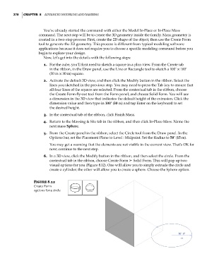
6. In a 3D view, click the Modify button in the ribbon, and then select the circle. From the
contextual tab in the ribbon, choose Create Form ➢ Solid Form. This will pop up two
visual options for you (Figure 8.12). One will allow you to simply extrude the circle and
create a cylinder; the other will allow you to create a sphere. Choose the Sphere option.
Figure 8.12
create form
options for a circle
c08.indd 278 05-05-2014 16:47:31