
Page 553 - Divyank Tyagi
P. 553
|
Creating CoMPlex Curtain Walls 519
6. In the Properties palette, set the U Grid Rotation value to 45 degrees and the V Grid
Rotation value to 45 degrees; then click Apply.
Notice how the modified values are updated in the 3D view with the Configure UV Grid
Layout command activated.
In the Configure UV Grid Layout mode (Figure 12.52), you will see a number of controls—all
of which relate to parameters you can also access in the Properties palette. The arrow cross in
the middle of the grid is the grid justification marker. You can drag it to any side, corner, or the
center of the grid, which will adjust the value of the Justification property of both U and V grids.
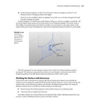
Figure 12.52
The uV grid
can be modified
directly or via
the values in
the Properties
palette.
The belts represent the lines along the surface from which the distance between grids is
measured. The distance is measured by chords, not curve lengths, and can be seen in the
Properties palette as the Belt Measurement parameter for both U and V grids.
Dividing the Surface with Intersects
As you have seen in the previous exercise, the Divide Surface tool allows you to divide the
surface of a form using the natural UVW grid of the surface. However, if you want to divide the
surface with a customized grid pattern, you divide it by intersecting geometry. By using the
Intersect feature, you can divide the surface based on the following:
◆ Intersecting levels, reference planes, and even lines drawn on a reference plane
◆ A mixture of U or V grids and intersects
Let’s take a look at an example based on our previous file, which will demonstrate how you
can use a series of defined reference planes to divide a surface:
c12.indd 519 5/3/2014 11:13:22 AM