
Page 604 - Divyank Tyagi
P. 604
570 | ChapTeR 13 Modeling Floors, Ceilings, and rooFs
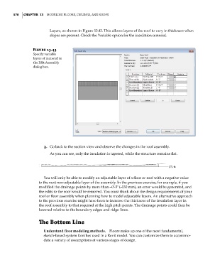
Layers, as shown in Figure 13.43. This allows layers of the roof to vary in thickness when
slopes are present. Check the Variable option for the insulation material.
Figure 13.43
specify variable
layers of material in
the edit assembly
dialog box.
3. Go back to the section view and observe the changes in the roof assembly.
As you can see, only the insulation is tapered, while the structure remains flat.
You will only be able to modify an adjustable layer of a floor or roof with a negative value
to the next non-adjustable layer of the assembly. In the previous exercise, for example, if you
modified the drainage points by more than –0ʹ-5ʺ (–130 mm), an error would be generated, and
the edits to the roof would be removed. You must think about the design requirements of your
roof or floor assembly when planning how to model adjustable layers. An alternative approach
to the previous exercise might have been to increase the thickness of the insulation layer in
the roof assembly to that required at the high pitch points. The drainage points could then be
lowered relative to the boundary edges and ridge lines.
The Bottom Line
Understand floor modeling methods. Floors make up one of the most fundamental,
sketch-based system families used in a Revit model. You can customize them to accommo-
date a variety of assumptions at various stages of design.
c13.indd 570 05-05-2014 16:57:20