
Page 623 - Divyank Tyagi
P. 623
|
Creating the Framework For a Family ComPonent 589
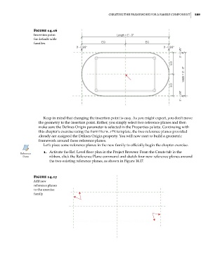
Figure 14.16
insertion point
for default table
families
Keep in mind that changing the insertion point is easy. As you might expect, you don’t move
the geometry to the insertion point. Rather, you simply select two reference planes and then
make sure the Defines Origin parameter is selected in the Properties palette. Continuing with
this chapter’s exercise using the Furniture.rft template, the two reference planes provided
already are assigned the Defines Origin property. You will now start to build a geometric
framework around these reference planes.
Let’s place some reference planes in the new family to officially begin the chapter exercise.
1. Activate the Ref. Level floor plan in the Project Browser. From the Create tab in the
ribbon, click the Reference Plane command and sketch four new reference planes around
the two existing reference planes, as shown in Figure 14.17.
Figure 14.17
add new
reference planes
to the exercise
family
c14.indd 589 5/3/2014 11:29:12 AM