
Page 618 - Divyank Tyagi
P. 618
584 | ChaptEr 14 Designing with the Family eDitor
Within the Family Editor, you also have the ability to include imported CAD data. From the
Insert tab in the ribbon, you can use the Import CAD tool to utilize 2D or 3D information from
another source. You cannot use the Link CAD tool in the Family Editor; therefore, any data
imported to a family will not update if the original CAD file is changed.
A feature in Revit is the ability to explode and then manipulate imported 3D solid CAD
geometry. You can experiment with this feature by downloading the file ImportCAD.sat from
this book’s web page at www.sybex.com/go/masteringrevit2015.
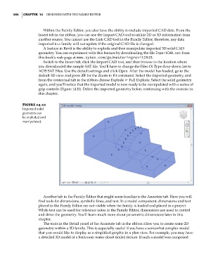
Switch to the Insert tab, click the Import CAD tool, and then browse to the location where
you downloaded the sample SAT file. You’ll have to change the Files Of Type drop-down list to
ACIS SAT Files. Use the default settings and click Open. After the model has loaded, go to the
default 3D view and press ZF for the Zoom to Fit command. Select the imported geometry, and
from the contextual tab in the ribbon choose Explode ➢ Full Explode. Select the solid geometry
again, and you’ll notice that the imported model is now ready to be manipulated with a series of
grip controls (Figure 14.11). Delete the imported geometry before continuing with the exercise in
this chapter.
Figure 14.11
imported solid
geometry can
be exploded and
manipulated.
Another tab in the Family Editor that might seem familiar is the Annotate tab. Here you will
find tools for dimensions, symbolic lines, and text. In a model component, dimensions and text
placed in the Family Editor are not visible when the family is loaded and placed in a project.
While text can be used for reference notes in the Family Editor, dimensions are used to control
and drive the geometry. You’ll learn much more about parametric dimensions later in this
chapter.
The tools in the Detail panel of the Annotate tab in the ribbon allow you to create some 2D
geometry within a 3D family. This is especially useful if you have a somewhat complex model
that you would like to display as a simplified graphic in a plan view. For example, you may have
a detailed 3D model of a bathroom water closet (toilet) fixture. If such a model was composed
c14.indd 584 5/3/2014 11:29:10 AM