
Page 636 - Divyank Tyagi
P. 636
602 | ChaptEr 14 Designing with the Family eDitor
Modeling techniques in the Family Editor
Creating complex geometry isn’t always as easy as opening the Family Editor and starting to
model the shape that you think you’re trying to create. Sometimes you need to model one form
in order to create another form. And sometimes you need to model a complex, parameterized
form in order to parameterize the actual shape that you’re trying to create. So that you
understand these advanced techniques, we’ll first cover the available geometry types that can be
created in Revit.
There are five discrete geometry types in the Family Editor: Extrusion, Sweep, Blend,
Revolve, and Swept Blend. Both solid and void forms can be modeled from these shapes. In this
section you’ll learn how to create all of these types, along with the Family Editor technique of
nesting families.
Which type you select is important, but our advice is to use the simplest form that will
express what you’re trying to model, keeping in mind how the geometry is likely to change.
Creating an Extrusion
Let’s get back to the furniture exercise where we are constructing a table. Activate the Ref. Level
floor plan, and from the Create panel in the ribbon click Extrusion. The first action we will take
is to specify a work plane to host the extrusion. If you don’t specify a work plane, the default
plane will be the level associated with the current view.
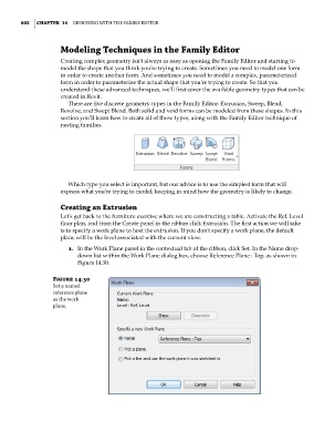
1. In the Work Plane panel in the contextual tab of the ribbon, click Set. In the Name drop-
down list within the Work Plane dialog box, choose Reference Plane : Top, as shown in
Figure 14.30.
Figure 14.30
set a named
reference plane
as the work
plane.
c14.indd 602 5/3/2014 11:29:15 AM