


Page 720 - Divyank Tyagi
P. 720
686   |  ChAPTer  16  Detailing Your Design


                             Refer to Chapter 2, “Applying the Principles of the User Interface and Project Organization,”
                             for more information about the difference between callouts and detail views.
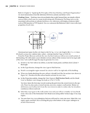
                             Drafting Views  Drafting views do not display the model. Instead, they are simply a blank
                             canvas within which you can create details using only 2D elements. Drafting views can be
                             associated with sections or callouts, but those view references will display a reference label
                             such as SIM (similar) or TYP (typical). You can customize the Reference Label value in the type
                             properties of each view.


                             Download and open the file c16-Sample-Building.rvt or c16-Sample-Metric.rvt from
                           this book’s companion website (www.sybex.com/go/masteringrevit2015).
                             From the Project Browser, activate the view Section 2 and you will see an overall section of
                           the building. We will create a more detailed section callout of the exterior wall at the right side
                           of the view. Let’s walk through the steps to generate this view.
                             1.  Switch to the View tab in the ribbon, locate the Create panel, and then click Callout ➢
                                Rectangle.
                             2.  In the Type Selector, change the view type to Wall Section.
                             3.  Sketch a rectangular region around the exterior wall at the right side of the building.

                             4.  When you finish sketching the new callout, it should look like the section view shown in
                                Figure 16.1. Double-click the callout head to activate the new view.
                             5.  In the Properties palette, change the View Name to Wall Section North, set the Detail
                                Level to Medium, and change the Scale to 1/2ʺ=1ʹ-0ʺ (1:25).

                                You have taken the first step toward creating the path from the overall down to the spe-
                                cific. From the plan and an overall section, you have created a wall section. Before we
                                drill down even further, let’s break the view down in order to isolate only the transition
                                conditions at floors and roof.
                             6.  Select the crop region in the wall section view and you will see a number of view break
                                icons. Click one of the Horizontal View Break icons along either vertical edge of the crop
                                region.
                             7.  You now have two crop subregions, but you will need to create one more. Select the crop
                                region again, and then click and drag the grip at the bottom of the upper subregion to
                                stretch it downward.


          c16.indd   686                                                                             5/3/2014   11:34:20 AM

