
Page 806 - Divyank Tyagi
P. 806
772 | ChApTer 18 AnnotAting Your Design
When any Dimension tool is active, you will see two settings available in the Options bar
that are specifically related to walls. The first drop-down list allows you to specify the default
method for dimensioning wall geometry. You can choose from wall centerlines, wall faces,
center of core, or faces of core. This setting merely establishes the defaults—what will be
selected when you first click a wall with the Dimension tool. If you need to select a different
part of a wall, hover the mouse cursor over a wall segment and then press the Tab key to cycle
through the available options. Each part of the wall segment geometry will highlight at the
mouse pointer as you continue to repeatedly press the Tab key.
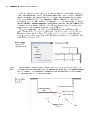
The second option allows you to pick either individual references (default) or entire
walls. When the Entire Walls option is selected, click the Options button to modify the Auto
Dimension settings, shown in Figure 18.30. In this example, we have chosen to dimension
opening widths as well as intersecting walls. The dimension string shown was placed with a
single click on the exterior wall!
Figure 18.30
using the Auto
Dimension option
Certification Once a dimension string is placed, you have several options to customize the string, the
Objective dimension values, and the witness lines (the linework that makes up the dimension). In Figure
18.31, you can see a typical aligned dimension string that has been selected after placement.
Let’s take a look at each of the available controls:
Figure 18.31
Controls for
dimensions
Dimension equality
toggle
Extension line grip
Witness line grip
Dimension value Dimension value
constraint grip
c18.indd 772 5/3/2014 11:56:00 AM