
Page 885 - Divyank Tyagi
P. 885
|
understanding lidar 851
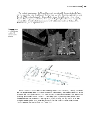
The next obvious step past the 3D model elements is creating 2D documentation. In Figure
21.2 you can see the point cloud for an industrial plant and all of the complex piping that runs
through it. This isn’t a photograph—it’s actually the image derived from the points within
the scan. This image was overlaid into Revit to create the piping layout next to it. Imagine the
amount of time it would take to measure and verify all this information in the field. With
the LiDAR scan, it’s all right there in 3D.
Figure 21.2
a lidar image
and the 3d
model derived
from it
Another common use of LiDAR in the modeling environment is to verify existing conditions
that you might already have modeled. Consider the need to verify the as-built conditions on an
active job site. Even as the construction industry has advanced to embrace building information
modeling (BIM) and 3D coordination, not everything gets installed or erected where it was
designed (for various reasons). A LiDAR scan can illustrate what has changed or what was
omitted from the model or construction. By overlaying the model with the scan, you can
visually compare the two, as shown in Figure 21.3.
c21.indd 851 5/3/2014 12:05:42 PM