Page 249 - Maxwell House
P. 249

Chapter 5                                                               229


                                                                2 2
                                                                 
                                                    Margin =    3   −  ∆ ⎫
                                                                         
                                                                    
                                                             �4 �  4
                                                                                     (5.67)
                                                                  2
                                                               4   4  ∆ ⎬
                                                      and     >  �
                                                            
                                                                        ⎭
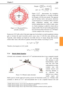
                                                 Figure 5.3.3    demonstrates  the  exemplary
                                                           15
                                                 image of RCS [dB] data vs. azimuth coordinate
                                                 for Douglas A-26 Invader aircraft. The apparent
                                                 goal of  military  tactics and  passive electronic
                                                 countermeasures is to minimize RCS of aircraft,
                                                 ships,  submarines,  missiles, and satellites
                                                 thereby making them less visible to radar, sonar,
                                                 etc. Such technology is called low observable or
                 Figure 5.3.3 Measured RCS vs.   simply stealth. One of such stealth approach has
                      azimuth coordinate         been discussed earlier in Section 2.8.1 of Chapter
                                                 2 in the example of the cloaking effect.

            Expression (5.67) tells us that if the radar range must be doubled, we need to quadruple antenna
            gain or increase the  peak transmitter  power  sixteen times  (!)  with the same antenna  gain.
            Typically,  radar antennas are high-cost and  bulky  devices of  unique design that  severely
            restricts their sizes or the effective aperture of the radar antenna. According to (5.49)

                                                      4 
                                          =   =                  (5.68)
                                               
                                          
                                                        2
            Therefore, the inequity in (5.67) yields
                                                  2
                                             >  � 4  ∆              (5.69)
                                          
                                                          
            5.3.4   Bistatic Radar Equation
            A bistatic radar schematic is shown in 5.3.4  and demonstrates how to use a separate transmit
                                               16
                                                                     (Tx) and receiving
                                                                     (Rx) antenna to catch
                                                                     backscattering signal.
                                                                     Note  that  such  radar
                                                                     configurations or more
                                                                     complex ones  with
                                                                     multiple transmit and
                                                                     receiving antennas is
                                                                     an   expensive   but

                         Figure 5.3.4 Bistatic radar schematic       effective way to detect
                                                                     stealth targets and
            build a passive missile approach warning systems for homeland security, etc. A bistatic radar
                                    17
            schematic  is shown  in  5.3.4   and  demonstrates  how to use a  separate  transmit  (Tx) and

            15  Public Domain Image, source: https://en.wikipedia.org/wiki/Radar_cross-section
            16  Public Domain Image, source: http://woof.tistory.com/217
            17  Public Domain Image, source: http://www.rfcafe.com/references/electrical/radar_eqn.htm
   244   245   246   247   248   249   250   251   252   253   254