
Page 253 - Maxwell House
P. 253
Chapter 5 233
1. Suitable selection of radiating elements forming LSAS. The traditional choice is the
electrical dipole in a shape of metal patch printed on array common dielectric substrate.
The surface of such patch is typically less than /2 x /2 = /4 depending on substrate
2
dielectric constant. In mm-wave range it means something around (15 – 100) mm . If so,
2
the extremely high density of conductivity current on the patch surface is expected that
leads to excessive Ohmic loss and consequently low antenna efficiency. Add the extra loss
in LSAS feeding network and expect the efficiency something around and below 50%.
2. Meanwhile, it is a well-established theoretically and practically fact that in mm-wave as
well optical band the power dissipation greatly diminishes as soon as all metal parts are
completely or partially excluded and replaced by elements manufactured from dielectric
with tanδ ≤ 10 . If so, a better candidate for array radiator might be an exceptionally
−4
broadband (octave and more) dielectric waveguide similar to one in Figure 6.3.4 of Chapter
a) b)
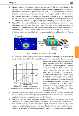
Figure 5.3.8 Dielectric waveguide as radiator
6. Careful choice of waveguide and substrate materials leads to high concertation of EM
energy inside waveguide as Figure 5.3.8a demonstrates reducing by that the expected
interactions between adjacent radiators of
highly populated MIMO array. The front end
of waveguide is cut as Figure 5.3.8 depicts
being open and matched to free space
creating down tilting pattern. It radiates the
same way as limited set of Huygens’
elements (look at Figure 4.3.9 from Chapter
4). Then the transmitting / receiving module
as well the interface to switching box could
be integrated with radiating elements of total
length in order of mm. The whole brick-
Figure 5.3.9 Average atmospheric architecture of array might be organized as
absorption of mm-waves at sea level, 20°C depicted in Figure 5.6.6a of Section 5.6 (see
later in this chapter).
3. Configuration and deployment of the arrays including the feed circuitry. It can be, for
example, the planar or circular phased array (conformal or more intricate 3D structure)
similar to be discussed later in Section 5.6 of this chapter.
4. Due to the tight placement, the mutual coupling, i.e. crosstalk interference between the
closely-packed antenna elements appears. As a result, the signal received or transmitted
each radiator is a vector sum of fractional signals received or transmitted by all its
neighbors. It makes the development of array and its beamformer a quite challenging task
requiring an all-inclusive LSAS electrodynamics simulation to estimate a-priori unknown