
Page 256 - Maxwell House
P. 256
236 ANTENNA BASICS
2 2
back to radar receiver = 3 . Here = () is the radar antenna gain. If so, the
�4 � 4
power supplied to radar receiver
2 2 4 2 2
() = 3 = 3 = 3 > ∆ (5.71)
4 4
4
�4 � 4 �4 � �4 �
would be maintained constant and exceeds the noise level for any target at a distance < .
In other words, the squared pattern is a means of achieving a more uniform signal strength at
the input of the receiver. Since the elevation angle , distance r and h are related as cos =
2
2
2
2
2
ℎ/, we can write ()~ = ℎ ⁄ cos = ℎ csc where ℎ = . If so, the pattern
envelope should remind (black curve in Figure 5.4.1e) the graph of function csc.
The last example in Figure 5.4.1f demonstrates the pattern of an antenna emitting a so-called
contour beam. Antennas with such a beam are typically an integral part of communication
satellites placed in Geostationary Orbit (GEO) [15] at an altitude of about 35,786 km (22,236
miles) directly over the Earth’s equator. Since the rotation period of these satellites and Earth
are the same their position over the Earth’s equator is almost permanent (with slight deviations).
Therefore, they can serve as motionless space relay stations bouncing communication and/or
broadcast signals from the Earth back to different geographical regions called
22
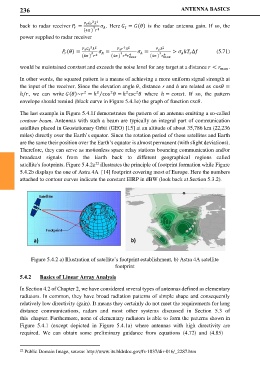
satellite's footprints. Figure 5.4.2a illustrates the principle of footprint formation while Figure
5.4.2b displays the one of Astra 4A [14] footprint covering most of Europe. Here the numbers
attached to contour curves indicate the constant EIRP in dBW (look back at Section 5.3.2).
a) b)
Figure 5.4.2 a) Illustration of satellite’s footprint establishment, b) Astra 4A satellite
footprint
5.4.2 Basics of Linear Array Analysis
In Section 4.2 of Chapter 2, we have considered several types of antennas defined as elementary
radiators. In common, they have broad radiation patterns of simple shape and consequently
relatively low directivity (gain). It means they certainly do not meet the requirements for long
distance communications, radars and most other systems discussed in Section 5.3 of
this chapter. Furthermore, none of elementary radiators is able to form the patterns shown in
Figure 5.4.1 (except depicted in Figure 5.4.1a) where antennas with high directivity are
required. We can obtain some preliminary guidance from equations (4.72) and (4.85)
22 Public Domain Image, source: http://www.its.bldrdoc.gov/fs-1037/dir-016/_2287.htm