
Page 357 - Maxwell House
P. 357
FEED LINE BASICS 337
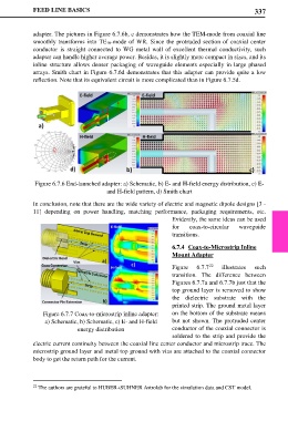
adapter. The pictures in Figure 6.7.6b, c demonstrates how the TEM-mode from coaxial line
smoothly transforms into TE10-mode of WR. Since the protruded section of coaxial center
conductor is straight connected to WG metal wall of excellent thermal conductivity, such
adapter can handle higher average power. Besides, it is slightly more compact in sizes, and its
inline structure allows denser packaging of waveguide elements especially in large phased
arrays. Smith chart in Figure 6.7.6d demonstrates that this adapter can provide quite a low
reflection. Note that its equivalent circuit is more complicated than in Figure 6.7.5d.
Figure 6.7.6 End-launched adapter: a) Schematic, b) E- and H-field energy distribution, c) E-
and H-field pattern, d) Smith chart
In conclusion, note that there are the wide variety of electric and magnetic dipole designs [3 -
11] depending on power handling, matching performance, packaging requirements, etc.
Evidently, the same ideas can be used
for coax-to-circular waveguide
transitions.
6.7.4 Coax-to-Microstrip Inline
Mount Adapter
22
Figure 6.7.7 illustrates such
transition. The difference between
Figures 6.7.7a and 6.7.7b just that the
top ground layer is removed to show
the dielectric substrate with the
printed strip. The ground metal layer
Figure 6.7.7 Coax-to-microstrip inline adapter: on the bottom of the substrate means
a) Schematic, b) Schematic, c) E- and H-field but not shown. The protruded center
energy distribution conductor of the coaxial connector is
soldered to the strip and provide the
electric current continuity between the coaxial line center conductor and microstrip trace. The
microstrip ground layer and metal top ground with vias are attached to the coaxial connector
body to get the return path for the current.
22 The authors are grateful to HUBER+SUHNER Astrolab for the simulation data and CST model.