
Page 393 - Maxwell House
P. 393
DISCONTINUITY IN FEED LINES 373
The complex coefficients arranged in a table are called scattering matrix or S-matrix in
th
short. Evidently, each coefficient shows how much of the incident wave in the j line
th
reaches the reference plane of the i line as the fraction of the total reflected wave . In general,
all coefficients in (7.6) are complex number and frequency dependable. The remarkable fact is
that 0 ≤ | | ≤ 1 that is the obvious consequence of the energy conservation law that prohibits
transferring outside a passive network more power than the outside sources delivered. For this
reason, S-matrix is a widespread basis for network analysis and synthesis with relatively easy
control of analytical and especially numerical algorithms. Now, let us take a closer look at (7.6).
Suppose the RF source is coupled to the j port only exerting the incident wave while there
th
are no RF sources in any other port, i.e. = 0, ≠ . Then according to (7.6)
= , = , … , = , … , =
2
2
1
1
Therefore,
⁄
⁄
⁄
1 = , 2 = , … , = , … , = ⁄ .
2
1
Consequently, the parameter can be treated as the transmission coefficient from the j port
th
1
th
to port1, as the transmission coefficient from the same j port to port2, and so on. We
2
demonstrated that all S-parameters have simple physical meaning, and their estimation comes
down to straightforward power measurements. Just inject energy of the dominant mode into
the j line and be sure that all lines work as semi-infinite ones, i.e. without slightest reflection
th
at any frequency. Meanwhile, any real-world lines are physically limited in length and thus
must be properly end-loaded with so-called matched loads or dummies. In general, any of such
load is the section of line filled with suitable lossy dielectric. The measurements are considered
highly accurate if the reflection coefficient of dummies is around 0.01.
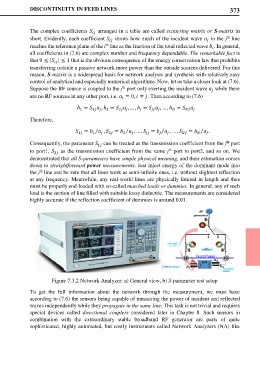
Figure 7.3.2 Network Analyzer: a) General view, b) S-parameter test setup
To get the full information about the network through the measurement, we must have
according to (7.6) the sensors being capable of measuring the power of incident and reflected
waves independently while they propagate in the same line. This task is not trivial and requires
special devices called directional couplers considered later in Chapter 8. Such sensors in
combination with the extraordinary stable broadband RF generator are parts of quite
sophisticated, highly automated, but costly instruments called Network Analyzers (NA) like