
Page 394 - Maxwell House
P. 394
374 Chapter 7
1
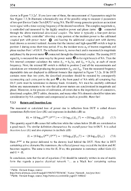
shown in Figure 7.3.2a . If you have one of them, the measurement of S-parameters might be
fun. Figure 7.3.2b illustrates schematically one of the possible setup to measure S-parameters
2
of two-port Device Under Test (DUT) using NA. The RF sweep generator produces an incident
wave signal with a time-varying frequency of the desired waveform. The complex magnitude
1
is controlled and measured by the highly sensitive power and phase meter connected
through the above-mentioned directional coupler. The latter is typically a four-port device
serves as a “traffic controller” directing a tiny portion of the incident power to the calibrated
coupled port with power meter and leaving the additional coupled port with dummy
load (shown as resistor) isolated. Assume that the internal and high-speed RF switch is kept in
position 1 during some short time period. If so, the incident wave of known magnitude and
1
phase reaches Port 1 of DUT. The reflected wave moves back and is measured (in magnitude
1
and phase) by the power meter connected through the directional coupler. The passing DUT
signal is measured the same way by the power meter in the right branch of NA. Then the
2
⁄
⁄
NA internal computer calculates the ratios 11 = and 21 = at each of swept
1
1
1
2
frequency. Next, the internal RF switch is shifted to position 2 and all the measurements and
calculations are reiterated producing the parameters and . Then the measured frequency
12
22
dependable data are displayed in different formats like depicted in Figure 7.3.2a. If the DUT
contains more than two ports, the described procedure should be repeated by consequently
reconnecting each extra port to the port at the front panel of NA while all remaining free
DUT ports must be terminated in dummy loads. Evidently, NA must be carefully calibrated
before any measurements to be sure that all power meters are synchronized in magnitude and
phase. Moreover, in the process of calibration, all errors due to the imperfection of connectors,
directional couplers, DUT cables, dummies, and many other NA elements should be taken into
consideration by NA computer and compensated as much as possible. Have fun!
7.3.3 Return and Insertion Loss
The measured or calculated loss of power due to reflection from DUT is called Return
(sometimes Reflection) Loss (RL) and expresses in decibels (dB) as
) = −10 log (| | ) = −20 log (| |) (7.7)
2
= 10 log ( ⁄ 10 11 10 11
10
This quantity equal 0 dB causes full reflection while the values below 20 dB are considered as
a good match. The similar definition characterizes the overall power loss in DUT. It is called
Insertion Loss (IL) and also expresses in decibels (dB)
2
= 10 log ( ⁄ ) = −10 log (| | ) = −20 log (| |) (7.8)
10 10 21 10 21
is the power delivered to the dummy load behind the DUT. Note that in DUT
Here
containing active elements like transistors, the reflected power may exceed the incident and RL
becomes negative. The same is true for IL. If so, this parameter is customary called Gain (G)
and G = -IL.
In conclusion, note that the set of equations (7.6) should be naturally written in one of matrix
form that regards a passive electrical network “… as a 'black box' containing various
1 Public Domain Image, source:
http://www.diytrade.com/china/pd/11596787/TD3618C_Vector_Network_Analyzer.html
2 Public Domain Image, source: http://www.ni.com/white-paper/11640/en/