
Page 117 - Schroeder - Hydraulic And Lube Filtration
P. 117
Base-Ported Pressure Fil ter MKF50
Type Fluid Appropriate Schroeder Media Fluid NF30
®
Petroleum Based Fluids All E Media (cellulose), Z-Media and ASP Media (synthetic) Compatibility NFS30
®
High Water Content All Z-Media and ASP Media (synthetic)
Invert Emulsions 10 and 25 µ Z-Media (synthetic), 10 µ ASP Media (synthetic) YF30
®
®
Water Glycols 3, 5, 10 and 25 µ Z-Media (synthetic) and all ASP Media (synthetic)
®
Phosphate Esters All Z-Media and all ASP Media (synthetic) with H (EPR) seal designation and 3 CFX30
and 10 µ E media (cellulose) with H (EPR) seal designation
Skydrol ® 3, 5, 10 and 25 µ Z-Media (synthetic) and all ASP Media (synthetic) with H.5 seal PLD
®
designation and W media (water removal) with H.5 seal designation (EPR seals and ®
stainless steel wire mesh in element, and light oil coating on housing exterior) Skydrol is a registered
trademark of Solutia Inc.
DF40
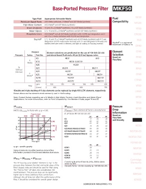
Element Element selections are predicated on the use of 150 SUS (32 cSt) Element CF40
Pressure Series Part No. petroleum based fluid and a 40 psi (2.8 bar) bypass valve. Selection
K3 4K3† 6K3 Based on PF40
E K10 4K10† & 6K10† Flow Rate
Media RFS50
K25 4K25†
To KZ1 4KZ1† 6KZ1† RF60
5000 psi
(345 bar) KZ3 4KZ3† 6KZ3†
Z- KZ5 4KZ5† 6KZ5† CF60
Media ®
KZ10 4KZ10† 6KZ10†
KZ25 4KZ25† 6KZ25† CTF60
gpm 0 100 120 140 160 180 200
Flow VF60
(L/min) 0 400 600 760
† Double and triple stacking of K-size elements can be replaced by single KK & 27K elements, respectively. LW60
Shown above are the elements most commonly used in this housing.
Note: Contact factory regarding use of E Media in High Water Content, Invert Emulsion and Water Glycol KF30
Applications. For more information, refer to Fluid Compatibility: Fire Resistant Fluids, pages 19 and 20.
TF50
∆P housing ∆P element Pressure KF50
MKF50 ∆P housing for fluids with sp gr = 0.86: ∆P element = flow x element ∆P factor x viscosity factor Drop
El. ∆P factors @ 150 SUS (32 cSt): Information KC50
2K 4K 6K Based on
Flow Rate
K3 .12 .06 .04 and Viscosity MKF50
K10 .05 .02 .02
K25 .01 .01 .01
KZ1 .10 .05 .03 KC65
KZ3/KAS3/KKAS3/27KAS3 .05 .03 .02
KZ5/KAS5/KKAS5/27KAS5 .04 .02 .01 NOF30-05
KZ10/KAS10/KKAS10/27KAS10 .03 .02 .01
KZ25 .02 .01 .01 NOF50-760
FOF60-03
1K 2K
sp gr = specific gravity
KZW1 .43 NMF30
Sizing of elements should be based on element flow KZW3 .32 .16
information provided in the Element Selection chart above. KZW5 .28 .14 RMF60
KZW10 .23 .12
∆P filter = ∆P housing + ∆P element KZW25 .14 .07 Cartridge
If working in units of bars & L/min, divide above
The ∆P housing curve labeled “Element Sizing” is the factor by 54.9. Elements
pressure drop between the inlet and outlet areas of the Viscosity factor: Divide viscosity by 150 SUS (32 cSt).
filter’s bypass valve and should be used for filter sizing. HS60
The “Port to Port” ∆P takes into consideration the
manifold block. This pressure drop can be significantly
higher due to these additional flow constrictions. MHS60
Although this ∆P does not affect the performance of the
filter, it should be con sidered for overall system design. KFH50
SCHROEDER INDUSTRIES 115