
Page 264 - Wago_AutomationTechnology_Volume3_2015_US.pdf
P. 264
750-479 / 753-479
4 2-Channel Analog Input Module ±10 V
262 Differential measurement input
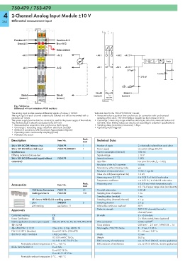
13 14
A
Function AI 1 C Function AI 2
B
Error AI 1 D Error AI 2
+E1 +E2
Data contacts
1 5
+AI 1 +AI 2 +AI 1 +AI 2 +AI 2
—E1 —E2 A Logic
D
2 6
-AI 1 -AI 2 -AI 1 -AI 2 -AI 2
270 pF Error
Function
270 pF
3 7
S S
4 8
Shield Shield
Shield Shield (screen) (screen)
(screen) (screen) 750-479
750-479
Fig. 750 Series
Delivered without miniature WSB markers
The analog input module receives differential signals of values ± 10VDC. Technical data for the 750-479/000-001 model:
The input signal of each channel is electrically isolated and will be transmitted with a • Measured-value acquisition time synchronous (in connection with synchronized
resolution of 13 bits. sampling of the slave, 750-303 Fieldbus Coupler (as from version 0101))
The system supply (via the data bus contacts) is used for the power supply of the module. • Overrange / measuring range underflow status byte, status bits, measured value and
The shield (screen) is directly connected to the DIN rail. LED (min./max. limiting values can also be set according to customers’ specifications)
• Measured-value acquisition: time synchronous (both inputs) • Sampling delay (instruction/conversion) < 50μs
• Overrange / measuring range underflow: status byte and LED • Operating mode triggered
• Method of conversion: SAR (Successive Approximation Register)
• Operating mode: continuously sampling (preset)
• Protection: RC circuit
Description Item No. Pack. Technical Data
Unit
2AI ±10V DC Diff. Measur. Inp. 750-479 1 Number of inputs 2, electrically isolated from each other
2AI ±10V DC Differential Input 750-479/000-001 1 Power supply via system voltage DC/DC
Synchronous Current consumption (internal) 100 mA
Differing technical data see text Signal voltage ± 10 V
2AI ±10V DC Differential Input (without 753-479 1 Internal resistance 1 MΩ
connector) Input filter low pass first order, f G = 5 kHz
Resolution of the A/D converter 14 bits
Monotonicy without missing codes yes
Resolution of measured value 13 bits + sign bit
Value of a LSB (least significant bit) 1.2 mV
Measuring error (25 °C) ≤ ± 0.05 % of the full scale value
Temperature coefficient < ± 0.01 % / K of the full scale value
Accessories Item No. Pack. Measuring error ≤ 0.4 % over whole temperature scale
Unit ≤ 0.1 % of upper range value (non-linearity)
753 Series Connectors 753-110 25 Crosstalk attenuation ≥ 80 dB
Coding elements 753-150 100 Sampling time of repetition 1 ms
Sampling delay (module) 1 ms
Miniature WSB Quick marking system Sampling delay (channel/channel) ≤ 1 μs
plain 248-501 5 Sampling duration ≤ 5 μs
with marking see Section 11 Admissible continuous overload 60 V
Approvals Dielectric strength 500 V DC channel/channel or
channel/system
Conformity marking 1 Bit width 2 x 16 bits data
Korea Certification 2 x 8 bits control/status (optional)
Marine applications (versions upon request) ABS, BV, DNV, GL, KR, LR, NKK, PRS, RINA Wire connection CAGE CLAMP ®
r UL 508 Cross sections 0.08 mm² ... 2.5 mm² / AWG 28 ... 14
r ANSI/ISA 12.12.01 Class I, Div. 2, Grp. ABCD, T4 Strip lengths, 750/753 Series 8 ... 9 mm / 0.33 in
TÜV 12.1297 X (Brasilien) Ex nA IIC T4 Gc (750-479) 9 ... 10 mm / 0.37 in
4 TÜV 07 ATEX 554086 X I M2 Ex d I Mb, Width 12 mm
II 3 G Ex nA IIC T4 Gc, Weight 54.5 g
II 3 D Ex tc IIIC T135°C Dc EMC immunity of interference acc. to EN 61000-6-2, marine applications
Permissible ambient temperature 0 °C ... +60 °C EMC emission of interference acc. to EN 61000-6-4, marine applications
IECEx TUN 09.0001 X Ex d I Mb,
Ex nA IIC T4 Gc,
Ex tc IIIC T135°C Dc
Permissible ambient temperature 0 °C ... +60 °C