Page 265 - Wago_AutomationTechnology_Volume3_2015_US.pdf
P. 265

750-476, 750-478 / 753-476, 753-478

           2-Channel Analog Input Module ±10 V/0-10 V                                                              4

           Single-ended (S.E.)                                                                                      263


                            13 14
                           A
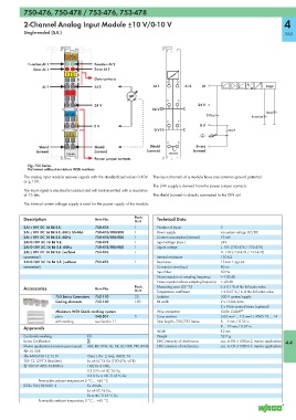
            Function AI 1      C       Function AI 2
                           B
              Error AI 1       D       Error AI 2
                            E1 E2
                                       Data contacts
                                                                    1    5                          A
                  AI 1                 AI 2                    AI 1         AI 2   AI                 D     Logic
                            +  +
                                                                    2    6

                                       24 V                                      24 V
                                                              24 V
                           0V  0V                                                    270 pF                 Error
                                                                                                      Function
                                                                    3    7

                                       0 V                                       0 V
                                                               0 V                           10 nF
                            S  S
                                                                    4    8
                 Shield                Shield                Shield             Shield
                (screen)               (screen)             (screen)           (screen)
                            750-476                                  750-476
                                       Power jumper contacts
            Fig. 750 Series
            Delivered without miniature WSB markers
           The analog input module receives signals with the standardized values 0-10V   The input channels of a module have one common ground potential.
           or ± 10V.
                                                               The 24V supply is derived from the power jumper contacts.
           The input signal is electrically isolated and will be transmitted with a resolution
           of 16 bits.                                         The shield (screen) is directly connected to the DIN rail.

           The internal system voltage supply is used for the power supply of the module.

           Description                 Item No.        Pack.    Technical Data
                                                       Unit
           2AI ±10V DC 16 Bit S.E.     750-476         1        Number of inputs          2
           2AI ±10V DC 16 Bit S.E. 60Hz S5-466  750-476/000-200  1  Power supply          via system voltage DC/DC
           2AI ±10V DC 16 Bit S.E. 60Hz  750-476/005-000  1     Current consumption (internal)  75 mA
           2AI 0-10V DC 16 Bit S.E.    750-478         1        Input voltage (max.)      24V
           2AI 0-10V DC 16 Bit S.E. 60Hz  750-478/005-000  1    Signal voltage            ± 10V (750-476 / 753-476)
           2AI ±10V DC 16 Bit S.E. (without   753-476  1                                  0 - 10V (750-478 / 753-478)
           connector)                                           Internal resistance       130 kΩ
           2AI 0-10V DC 16 Bit S.E. (without   753-478  1       Resolution                15 bits + sign bit
           connector)                                           Conversion time (typ.)    80 ms
                                                                Input filter              50 Hz
                                                                Noise rejection at sampling frequency  < -100 dB
                                                                Noise rejection above sampling frequency  < -40 dB
           Accessories                 Item No.        Pack.    Measuring error (25 °C)   ≤ ± 0.1 % of the full scale value
                                                       Unit     Temperature coefficient   < ± 0.01 % / K of the full scale value
                       753 Series Connectors  753-110  25       Isolation                 500 V system/supply
                       Coding elements  753-150        100      Bit width                 2 x 16 bits data
                                                                                          2 x 8 bits control/status (optional)
                       Miniature WSB Quick marking system       Wire connection           CAGE CLAMP ®
                       plain           248-501         5        Cross sections            0.08 mm² ... 2.5 mm² / AWG 28 ... 14
                       with marking    see Section 11           Strip lengths, 750/753 Series  8 ... 9 mm / 0.33 in
           Approvals                                                                      9 ... 10 mm / 0.37 in
                                                                Width                     12 mm
           Conformity marking       1                           Weight                    52.7 g
           Korea Certification                                  EMC immunity of interference  acc. to EN 61000-6-2, marine applications  4.4
           Marine applications (versions upon request)  ABS, BV, DNV, GL, KR, LR, NKK, PRS, RINA  EMC emission of interference  acc. to EN 61000-6-4, marine applications
           r UL 508
           r ANSI/ISA 12.12.01      Class I, Div. 2, Grp. ABCD, T4
           TÜV 12.1297 X (Brasilien)  Ex nA IIC T4 Gc (750-476, -478)
           4 TÜV 07 ATEX 554086 X   I M2 Ex d I Mb,
                                    II 3 G Ex nA IIC T4 Gc,
                                    II 3 D Ex tc IIIC T135°C Dc
                 Permissible ambient temperature 0 °C ... +60 °C
           IECEx TUN 09.0001 X      Ex d I Mb,
                                    Ex nA IIC T4 Gc,
                                    Ex tc IIIC T135°C Dc
                 Permissible ambient temperature 0 °C ... +60 °C
   260   261   262   263   264   265   266   267   268   269   270