Page 266 - Wago_AutomationTechnology_Volume3_2015_US.pdf
P. 266

750-477 / 753-477

   4    2-Channel Analog Input Module 0-10 V AC/DC

  264   Differential inputs


                         13  14
                         A
          Function AI 1      C       Function AI 2
                         B
            Error AI 1       D       Error AI 2
                         +E1 +E2
                                     Data contacts
                                                                  1   5                120 Ω
               +AI 1                 +AI 2                  +AI 1         +AI 2   +AI
                         —E1 —E2                                                                  A
                                                                                        270 Ω             Logic
                                                                                                    D
                                                                  2   6
               -AI 1                 -AI 2                  -AI 1         -AI 2   -AI
                                                            24 V                                          Error
                                                                                    10nF   10nF     Function
                                                                  3   7

                                                             0 V
                          S  S
                                                                  4   8
              Shield                 Shield                Shield             Shield
             (screen)                (screen)             (screen)          (screen)
                          750-477                                  750-477
                                     Power jumper contacts
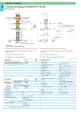
          Fig. 750 Series
          Delivered without miniature WSB markers
        The analog input module receives AC and DC voltages of values 0-10V eff.  The fieldside and internal system are electrically isolated.
        The module measures the rms value of the voltage and displays it with a   The system supply (via the data bus contacts) is used for the power supply of
        resolution of 1mV.                                  the module.

        The maximum voltage must not exceed 20V.            The input channels are differential inputs.
        The differential inputs are electrically isolated.  The shield (screen) is directly connected to the DIN rail.
        Description                  Item No.        Pack.    Technical Data
                                                     Unit
        2AI 0-10V AC/DC Differential Input  750-477  1        Number of inputs         2
        2AI 0-10V AC/DC Diff. (without connector)  753-477  1  Power supply            via system voltage DC/DC
                                                              Current consumption (internal)  80 mA
                                                              Signal voltage           0 V ... 10 V eff. (peak value 20 V)
                                                              Internal resistance      120 kΩ
                                                              Resolution               16 bits internal (1 LSB = 1 mV)
                                                              Conversion time          200 ms
                                                              Measuring error (25 °C)  < ± 0.1 % of the full scale value
                                                              Temperature coefficient  < ± 110 ppm / K of the full scale value
                                                              Error in complete temperature range  ≤ ± 0.6 % of the full scale value
                                                              Dielectric strength       500 V DC channel/channel or
                                                                                       channel/system
        Accessories                  Item No.        Pack.    Voltage via power jumper contacts  24 V DC
                                                     Unit     Bit width                2 x 16 bits data
                     753 Series Connectors  753-110  25                                2 x 8 bits control/status (optional)
                     Coding elements  753-150        100      Process data             0.0 V is 0x0000; 20 V DC is 0x4E20
                                                              Wire connection          CAGE CLAMP ®
                     Miniature WSB Quick marking system       Cross sections           0.08 mm² ... 2.5 mm² / AWG 28 ... 14
                     plain           248-501         5        Strip lengths, 750/753 Series  8 ... 9 mm / 0.33 in
                     with marking    see Section 11                                    9 ... 10 mm / 0.37 in
        Approvals                                             Width                    12 mm
                                                              Weight                   50.3 g
        Conformity marking        1                           EMC immunity of interference  acc. to EN 61000-6-2
        Korea Certification                                   EMC emission of interference  acc. to EN 61000-6-4
        r UL 508
        r ANSI/ISA 12.12.01       Class I, Div. 2, Grp. ABCD, T4
        4 TÜV 07 ATEX 554086 X    I M2 Ex d I Mb,
                                  II 3 G Ex nA IIC T4 Gc,
                                  II 3 D Ex tc IIIC T135°C Dc
              Permissible ambient temperature 0 °C ... +60 °C
        IECEx TUN 09.0001 X       Ex d I Mb,
                                  Ex nA IIC T4 Gc,
                                  Ex tc IIIC T135°C Dc
              Permissible ambient temperature 0 °C ... +60 °C
   261   262   263   264   265   266   267   268   269   270   271