
Page 17 - Parker - AC890/AC890PX series
P. 17
Modular Systems Drives
AC890 Systems Drive
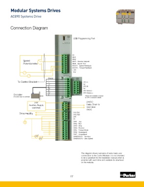
Connection Diagram
USB Programming Port
0V
AIN1
AIN2
Speed AIN3 - Remote Setpoint
Potentiometer AIN4 - Speed Trim
AOUT1 - Speed Feedback
AOUT2 - Torque Feedback
+10V
-10V
Shield
To Control Bracket - + STO A
Z/ 0V
Z STO B
B/ 0V
B STO Status -
A/ STO Status +
Encoder A
(Encoder input is optional) Please see installation manual
for STO connection details
24V 24VDC
Auxiliary Supply Daisy Chain to
(optional) next drive
0VDC
Drive Healthy DOUT3A
DOUT3B
24V
0V
DIN1 - Jog
DIN2 - Run
DIN3 - Stop
DIN4 - Reverse
DIN5 - Torque Mode
DIN6 - Unassigned
+ DIN7 - Unassigned
DR + DIN8/DOUT1 - Running
ZS DIN9/DOUT2 - Zero Speed
This diagram shows examples of some basic user
connections to the Control Module. It is not intended
to be a substitute for the installation manual which is
provided with each drive and available for download
on the website.
17