
Page 3 - Destaco - Parallel Shaft/Flange Drives
P. 3
P Series
Parallel Shaft/Flange Drives | How To Order
Indexer Ordering Procedure Reducer Ordering Procedure
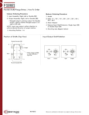
Position of Shafts (Top View)Position of Shafts (Top View)
1. Input Assembly: Right, Left or Double (DE) 1. Model Indexer Mounting Position Indexer Mounting Position
2. Output Assembly: Right, Left or Double (DE). 2. Ratio: 5:1, 10:1, 15:1, 20:1, 25:1, 30:1, 40:1, 1 1 2 2
Double Extended (DE)
Double Extended (DE)
• Flanged output is primary output. For Double 50:1, 60:1 AE: AE:
R
Output, specify whether flanged output is on 3. Motor Adapter L R L
right or left side. AE: AE:
4. Reducer Input Shaft Extension: Single Input (SE) Output AS: AS:
Output
NOTE: Input may rotate in either direction to or Double Input (DE)
achieve desired direction of output rotation. AS: AS:
5. Mounting (see diagram below)
3. Mounting Position: 1-6 Input Input NOTE: Flange available NOTE: Flange available
on either Left side or
on either Left side or
Right side. Right side.
3 3 4 4
Position of Shafts (Top View) Input/Output Shaft Rotation L R L AE: AE:
R
Position of Shafts (Top View) Indexer Mounting Position AE: AE:
Double Extended (DE) Double Extended (DE) AS: AS:
Double Extended (DE)
1 2 AS: AS:
R L AE:
AE:
Output AS: 5 5 6 AS: 6 AS:
AE: AE:
AS:
NOTE: Flange available
Input on either Left side or
Right side.
3 4 AS: AS:
Input Output Input Input Output Input Output AE: AE:
Output
R L AE:
AE: AE: Input Shaft AE: Input Shaft AS: Output Shaft
AS: Output Shaft
Double Extended (DE) AS:
AS:
5 6 AS:
AE:
AS:
Input Output Input Output AE:
AE: Input Shaft AS: Output Shaft
IN-PAR-3 Dimensions and technical information are subject to change without notice