
Page 24 - Parker - Flow Control Valves
P. 24
Catalog HY15-3502/US P.C. Flow Control Valve
Technical Information Series J04C2
CV
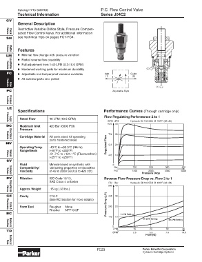
General Description
Restrictive Variable Orifice Style, Pressure Compen-
sated Flow Control Valve. For additional information
Valves
Check
SH see Technical Tips on pages FC1-FC4.
Features
Valves
Shuttle
LM • Minimal flow change with pressure variation
• Partial reverse flow capability
• Full adjustment from 1-40 LPM (0.3-10.6 GPM)
• Hardened working parts for maximum durability (2)
Controls
Load/Motor
FC • Adjustable and tamperproof versions available Inlet Outlet
(1) (2)
• All external parts zinc plated
(1)
Flow
Controls
PC Adjustable Style
Pressure
Controls
LE
Specifications Performance Curves (Through cartridge only)
Flow Regulating Performance 2 to 1
Rated Flow 40 LPM (10.6 GPM)
GPM LPM Hydraulic Oil 150 SSU @ 100°F (32 cSt)
Elements
Logic
10.6 40
DC Maximum Inlet 420 Bar (6000 PSI)
Pressure
7.9 30
Cartridge Material All parts steel. All operating
parts hardened steel.
Directional
Controls
MV Regulated Flow 5.3 20
Operating Temp. -40°C to +93.3°C (Nitrile)
Range/Seals (-40°F to +200°F)
-31.7°C to +121.1°C (Fluorocarbon)
2.6 10
(-25°F to +250°F)
Valves
Manual
SV
Fluid Mineral-based or synthetic with 0
Compatibility/ lubricating properties at viscosities Bar 100 200 300 400
0
Viscosity of 45 to 2000 SSU (6 to 420 cSt) PSI 1450 2900 4350 5800
Pressure Drop
Solenoid
Valves
PV Filtration ISO Code 16/13, Reverse Flow Pressure Drop vs. Flow 2 to 1
SAE Class 4 or better
PSI Bar Hydraulic Oil 150 SSU @ 100°F (32 cSt)
580 40
Approx. Weight .15 kg (.33 lbs.)
Valves
Proportional
P)
CE Cavity C10-2 435 30
(See BC Section for more details)
Form Tool Rougher None Pressure Drop ( 290 20
Finisher NFT10-2F
Coils &
Electronics
BC 2 LPM Setting
145 10
20 LPM Setting 40 LPM Setting
0
Cavities
Bodies &
LPM 10 20 30 40
TD 0
GPM 2.6 5.3 7.9 10.6
Flow (Q)
Data
Technical
FC23 Parker Hannifin Corporation
Hydraulic Cartridge Systems