
Page 20 - Exlar - GSM series integrated servo motor and actuator
P. 20
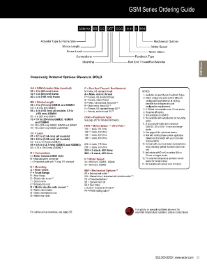
GSM Series Ordering Guide

                                          Sample Product Number: GSM30-0405-MFA-KM5-218-30-PBXL


                                               GSM AA BB   CC DEF GGG HHH II MM


                         Actuator Type & Frame Size                                         Mechanical Options
                                      Stroke Length                                        Motor Speed
                                         Screw Lead                                      Motor Stator
                                              Connections                        Feedback Type
                                                  Mounting                   Rod End Thread/Rod Material
                                                                                                                        GSM Series


                   Commonly Ordered Options Shown in BOLD


                   AA = GSM Actuator Size (nominal)  F = Rod End Thread / Rod Material
                   20 = 2 in (60 mm) frame         M = Male, US standard thread      NOTES:
                   30 = 3 in (80 mm) frame         A = Male, metric thread             1.  Available as described in Feedback Types.
                   40 = 4 in (100 mm) frame        F = Female, US standard thread      2.  Stator voltage and pole options allow for
                                                   B = Female, metric thread           catalog rated performance at varying
                   BB = Stroke Length              W = Male, US standard thread SS  10  amplifier bus voltages and pole
                   03 = 3 in (76 mm) GSM20 and GSM30  R = Male metric thread SS  10    configuration requirements.
                   04 = 4 in (102 mm) GSM40        V = Female, US standard thread SS  10    3.  0.75 lead not available over 12 inch stroke
                   06 =  6 in (152 mm) all models; 5.9 in    L = Female, metric thread SS  10    4. Requires AR option
                      (150 mm) GSM30                                                   5.  Not available on GSM20.
                   08 = 8 in (203 mm) GSM40        GGG = Feedback Type                 6.  Not available with extended tie rod mounting
                   10 = 10 in (254 mm) GSM20, GSM30    See page 207 for detailed information.  option.
                      and GSM40                                                       7.   A second anti-rotate arm is used on
                   12 = 12 in (305 mm) GSM20, GSM30 and GSM40  HHH = Motor Stator   – All 8 Pole  8   GSM 20, 30 & 40 for 10 inch and longer
                                                                 2
                   18 = 18 in (457 mm) GSM30 and GSM40  118 = 1 stack, 115 Vrms         stroke.
                                                   138 = 1 stack, 230 Vrms             8.  See page 48 for optimized stators.
                   CC = Lead                       158 = 1 stack, 400 Vrms
                   01 = 0.1 in (2.54 mm) (all models)                                  9.  N/A with holding brake unless application
                   02 = 0.2 in (5.08 mm) (all models)  168 = 1 stack, 460 Vrms         details are discussed with your local ales
                   04 = 0.4 in (10.16 mm) (GSM20)                                      representative.
                   05 = 0.5 in  (12.7 mm) (GSM30 and GSM40)  218 = 2 stack, 115 Vrms   10.  Consult with your local sales representative
                   08 = 0.75 in (19.05 mm) (GSM40)  3  258 = 2 stack, 230 Vrms         when ordering splined stainless steel main
                                                   238 = 2 stack, 400 Vrms             rod.
                   D = Connections                 268 = 2 stack, 460 Vrms           11.  Anti-rotate with D or K mounting N/A on
                   I = Exlar standard M23 style                                        10 inch or longer stroke.
                   M = Manufacturer’s connector  1  II = Motor Speed                 12. For extended temperature operation consult
                   J = Embedded leads with “I” plug, 3 ft. standard  30 = 3000 rpm, GSM30,  GSM40     factory for model number.
                                                   50 = 5000 rpm, GSM20              13. Not available with splined main rod option
                   E = Mounting
                   C = Rear clevis                 MM =  Mechanical Options  12
                   F = Front flange                AR = External anti-rotate  7
                   R = Rear flange                 HW = Manual drive, Handwheel with interlock switch  5, 9
                   D = Double side mount  11       PB = Protective bellows  6
                   T = Side trunnion               SR =  Splined main rod
                   E = Extended tie rods           RB = Rear brake
                   K = Metric double side mount  11  L1/L2/L3 = External limit switch  4
                   Q = Metric side trunnion        P5 = IP65S sealing option 13
                   M = Metric extended tie rods
                   G = Metric rear clevis


                                                                                 For options or specials not listed above or for
                   For cables and accessories, see page 202.                     extended temperature operation, please contact Exlar


                                                                                              952.500.6200 | www.exlar.com    55