
Page 24 - Parker - General Technical
P. 24
4300 Catalog General Technical
Pressure P
Return
To
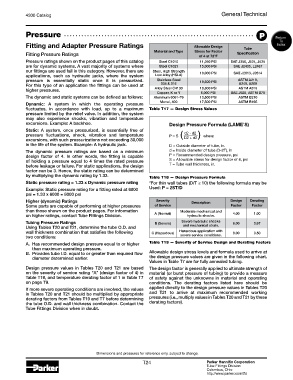
Fitting and Adapter Pressure Ratings Allowable Design Index
Material and Type Stress for Factor Tube
Fitting Pressure Ratings of 4 at 72°F Specification
Pressure ratings shown on the product pages of this catalog Steel C1010 11,250 PSI SAE J356, J524, J525
are for dynamic systems. A vast majority of systems where Steel C1021 15,000 PSI SAE J2435, L2467
our fittings are used fall in this category. However, there are Steel, High Strength
applications, such as hydraulic jacks, where the system Low Alloy (HSLA) 18,000 PSI SAE J2613, J2614
pressure is essentially static once it is pressurized. Stainless Steel 18,800 PSI ASTM A213,
For this type of an application the fittings can be used at 304 & 316 A249, A269
higher pressures. Alloy Steel C4130 18,800 PSI ASTM A519
Copper, K or Y 6,000 PSI SAE J528, ASTM B75
The dynamic and static systems can be defined as follows: Aluminum 6061-T6 10,500 PSI ASTM B210
Dynamic: A system in which the operating pressure Monel, 400 17,500 PSI ASTM B165
fluctuates, in accordance with load, up to a maximum Table T17 — Design Stress Values
pressure limited by the relief valve. In addition, the system
may also experience shocks, vibration and temperature
excursions. Example: A backhoe. Design Pressure Formula (LAME’S)
Static: A system, once pressurized, is essentially free of
pressure fluctuations, shock, vibration and temperature P = S ( d2 - d2 ) where:
excursions, with such pressurizations not exceeding 30,000 D2 + d2
in the life of the system. Example: A hydraulic jack. D = Outside diameter of tube, in.
The dynamic pressure ratings are based on a minimum d = Inside diameter of tube (D-2T), in
design factor of 4. In other words, the fitting is capable P = Recommended design pressure, psi
of holding a pressure equal to 4 times the rated pressure S = Allowable stress for design factor of 4, psi
before leakage or failure. For static applications, the design T = Tube wall thickness, in.
factor can be 3. Hence, the static rating can be determined
by multiplying the dynamic rating by 1.33. Table T18 — Design Pressure Formula
Static pressure rating = 1.33 x Dynamic pressure rating *For thin wall tubes (D/T ≥ 10) the following formula may be
Example: Static pressure rating for a fitting rated at 6000 Used: P = 2ST/D
psi = 1.33 x 6000 = 8000 psi
Higher (dynamic) Ratings Severity Description Design Derating
Some parts are capable of performing at higher pressures of Service Factor Factor
than those shown on the product pages. For information Moderate mechanical and
on higher ratings, contact Tube Fittings Division. A (Normal) hydraulic shocks. 4.00 1.00
Tubing Pressure Ratings B (Severe) Severe hydraulic shocks 6.00 0.67
Using Tables T20 and T21, determine the tube O.D. and and mechanical strain.
wall thickness combination that satisfies the following C (Hazardous) Hazardous application with 8.00 0.50
two conditions: severe service conditions.
A. Has recommended design pressure equal to or higher Table T19 — Severity of Service Design and Derating Factors
than maximum operating pressure.
B. Provides tube I.D. equal to or greater than required flow Allowable design stress levels and formula used to arrive at
diameter determined earlier. the design pressure values are given in the following chart.
Values in Table T7 are for fully annealed tubing.
Design pressure values in Tables T20 and T21 are based The design factor is generally applied to ultimate strength of
on the severity of service rating “A” (design factor of 4) in material (or burst pressure of tubing) to provide a measure
Table T19, and temperature derating factor of 1 in Table T7 of safety against the unknowns in material and operating
on page T9. conditions. The derating factors listed here should be
If more severe operating conditions are involved, the values applied directly to the design pressure values in Tables T20
in Tables T20 and T21 should be multiplied by appropriate and T21 to arrive at maximum recommended working
derating factors from Tables T19 and T7 before determining pressures (i.e., multiply values in Tables T20 and T21 by these
the tube O.D. and wall thickness combination. Contact the derating factors).
Tube Fittings Division when in doubt.
Dimensions and pressures for reference only, subject to change.
T24 Parker Hannifin Corporation
Tube Fittings Division
Columbus, Ohio
http://www.parker.com/tfd