
Page 34 - Parker - L90LS Mobile directional control valve
P. 34
Catalogue HY17-8504/UK Mobile Directional Control Valve
Spool Section L90LS
System functions B A
The L90LS can be equipped with integrated functions to create
complete system solutions. The load signal from any service port
or spool section can be connected with signal ducts and utilized
to stop or limit the pressure to individual machine functions. Two speed line
In cranes, this auxiliary controlling concept is implemented T
with the aid of the M11 function manifold [90]. Another example P
of how the load-signal ducts can be exploited is in the control of
thrust pressure to rock drills, according to the instantaneous rota-
tional torque (rotation-pressure controlled thrust).
System signal lines [80]
SF Valve section equipped with 3 signal lines that can be
connected internally to individual load signals [81] from LS LS
service port. Signal line for activation of two-speed func- T
tion [82] . 3
/ No signal lines. 2 Signal lines
1
LSB LSA
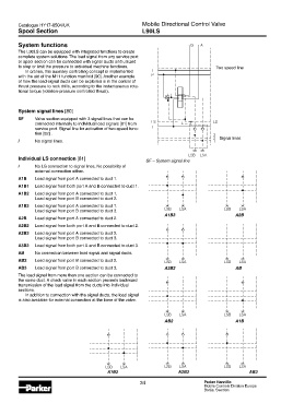
Individual LS connection [81] SF – System signal line
/ No LS connection to signal lines. No possibility of
external connection either.
A1B Load signal from port A connected to duct 1.
A1B1 Load signal from both port A and B connected to duct 1.
A1B2 Load signal from port A connected to duct 1.
Load signal from port B connected to duct 2.
A1B3 Load signal from port A connected to duct 1.
Load signal from port B connected to duct 3. LSB LSA LSB LSA
A1B3 A2B
A2B Load signal from port A connected to duct 2.
A2B2 Load signal from both port A and B connected to duct 2.
A2B3 Load signal from port A connected to duct 2.
Load signal from port B connected to duct 3.
A3B3 Load signal from both port A and B connected to duct 3.
AB No connection between load signal and signal ducts.
AB2 Load signal from port B connected to duct 2. LSB LSA LSB LSA
AB3 Load signal from port B connected to duct 3. A2B2 AB
The load signal from more than one section can be connected to
the same duct. A check valve in each section prevents backward
transmission of the load signal from the ducts into individual
sections.
In addition to connection with the signal ducts, the load signal
is also available for external connection at the base of the valve.
LSB LSA LSB LSA
AB2 A1B
LSB LSA LSB LSA LSB LSA
A1B2 A2B3 AB3
34 Parker Hannifin
Mobile Controls Division Europe
Borås, Sweden