
Page 29 - Parker - L90LS Mobile directional control valve
P. 29
Catalogue HY17-8504/UK Mobile Directional Control Valve
Choice of spool L90LS
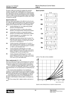
The spool is the most important link between the operator’s Spool symbols
actuation of a control lever and the behaviour of the corre-
sponding machine function. The designs of our spools are there- B A
fore customized to meet the operating criteria of each individual
machine function as accurately as possible. Spools are designed D
with the aid of a computerized specification system, which takes
all factors into account.
Spool function [60] EA
There are many spool variants: D, EA, EB, M, CA, Dm, Da and
Db, which are customized for different flows, load conditions and
actuator area ratios. The spools are also available with different
degrees of force feedback from the A- and/or B-side [64 A/B]. EB
D Double-acting spool for, e.g. double-acting cylinder.
Blocked in the neutral position.
M
EA Single-acting spool for, e.g. single-acting cylinder.
Blocked in the neutral position. Service port B blocked.
EB Single-acting spool for, e.g. single-acting cylinder.
Blocked in the neutral position. Service port A blocked. CA
M Double-acting spool for, e.g. hydraulic motor. Float
position function in neutral position.
CA Regenerative spool for saving oil from the pump. The Dm
large side of the cylinder is connected to the A-port. Oil
from the B port is passed to the A port and not to the
tank when P is connected to A.
Da
Dm Double-acting spool with drainage A to T and B to T,
which prevents pressure build-up in the neutral position.
The spool is used as a double-acting spool in combina-
tion with, e.g. an overcentre valve. Db
Da Double-acting spool with drainage A to T, which
prevents pressure build-up in the A-port in the neutral P T
position. The spool is used as a double-acting spool in
combination with, e.g. an overcentre valve.
Db Double-acting spool with drainage B to T, which
prevents pressure build-up in the B-port in the neutral
position. The spool is used as a double spool in combi-
nation with, e.g. an over-centre valve. q (l/min) Flow rate in motor connection
Flow requirements [61 A, B]
There is a wide range of function optimized spool for the L90LS
with nominal flows of up to 90 l/min per spool-section when the
sections are equipped with individual pressure-compensators.
Without individual pressure-compensators, flows up to 125
l/min per spool section are obtainable, depending on the adjusted
differential between the load-signal pressure and the pump pres-
sure.
On the basis of the desired flows to the A and B ports
entered in the ordering documentation, our computerized valve-
specification system selects a spool to give at least the specified
flow, at the same time taking all other parameters into account.
The maximum flow is then set by limiting the spool stroke
by means of adjustment screws on the spool actuators or, in
the case of electro-hydraulic remote control, by tuning the elec-
tronics.
See “Flow settings [72]” for details on factory-set maximum
flows.
Spool stroke (mm)
Typical curves showing flow as a function of spool stroke.
29 Parker Hannifin
Mobile Controls Division Europe
Borås, Sweden