
Page 30 - Parker - L90LS Mobile directional control valve
P. 30
Catalogue HY17-8504/UK Mobile Directional Control Valve
Choice of spool L90LS
Area ratios [62] F
The area ratio for a spool section is calculated by dividing
the cylinder area that is connected to the B-port by the area
connected to the A-port. When the large side of the cylinder is
connected to the A-port, the area ratio is less than 1. The area
ratio for a motor is 1. A B
LAB - Lift load can change between the A- and B-port.
F
A B
Load characteristics [63]
The characteristics of the lift load can be specified according to P T
five typical cases. This information is entered so that the spool LA - Lift load normally on A-port only.
can be be customized optimally for the intended application.
LAB Lift load can alternate between A-port and B-port.
F
LA Lift load normally on A-port only.
LB Lift load normally on B-port only.
LN No or low lift-load on A- and B-ports.
S Slewing function. A B
P T
LB - Lift load normally on B-port only.
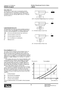
Force feedback [64 A, B]
The L90LS can be furnished with a force-feedback function to
give operators of the LS system the same positive sense of
force-control obtained with constant-flow (CFO) systems. This
makes it easier for the operator to avoid damaging the machine in
applications such as digging, since he is able to sense increasing
resistance or outright obstacles to the movement of a machine
function.
Force feedback also gives a kind of ramp function that results
in more gentle transition between rapid changes in the speed
of a machine movement. This in turn has a stabilizing effect Flow rate (%) Force feedback
on the hydraulic system and results in smoother operation of
the machine. Both characteristics are important, especially for
functions like slewing movements. In addition to increasing the
efficiency of the machine, they also minimize wear.
The A and B ports individually can be given any one of three
different levels of force feedback. The higher the level, the greater
the reduction in speed for a given lever stroke as resistance Light
rises. This means that the operator must move the lever further if load
he wishes to maintain the same speed of movement with rising
resistance. Heavy
/ No force feedback load
FN Normal level of force feedback
FH High level of force feedback
FL Low level of force feedback
The force feedback function is not available for directly operated Lever stroke (%)
valves.
30 Parker Hannifin
Mobile Controls Division Europe
Borås, Sweden