
Page 29 - Apollo - Industrial Applications Guide
P. 29
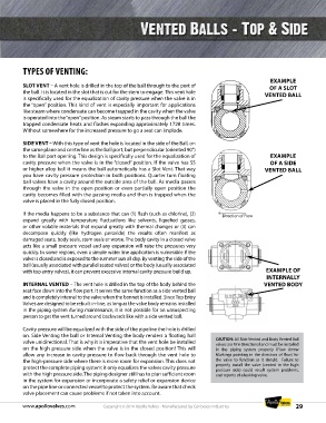
TYPES OF VENTING:

                                                                                                       EXAMPLE
          SLOT VENT – A vent hole is drilled in the top of the ball through to the port of            OF A SLOT
          the ball. It is located in the slot that is cut for the stem to engage. This vent hole    VENTED BALL
          is specifically used for the equalization of cavity pressure when the valve is in
          the “open” position. This kind of vent is especially important for applications
          like steam where condensate can become trapped in the cavity when the valve
          is operated into the “open” position. As steam starts to pass through the ball the
          trapped condensate heats and flashes expanding approximately 1728 times.
          Without somewhere for the increased pressure to go a seat can implode.

          SIDE VENT – With this type of vent the hole is located in the side of the Ball, on
          the same plane and centerline as the ball port, but perpendicular (oriented 90°)
          to the Ball port opening. This design is specifically used for the equalization of           EXAMPLE
          cavity pressure when the valve is in the “closed” position. If the valve has SS             OF A SIDE
          or higher alloy ball it means the ball automatically has a Slot Vent. That way            VENTED BALL
          you have cavity pressure protection in both positions. Quarter turn floating
          ball valves have a cavity around the outside area of the ball. As media passes
          through the valve in the open position or even partially open position the
          cavity becomes filled with the passing media and then is trapped when the
          valve is placed in the fully closed position.

          If the media happens to be a substance that can (1) flash (such as chlorine), (2)   Direction of Flow
          expand  greatly  with temperature fluctuations  like  solvents,  liquefied  gasses,
          or other volatile materials that expand greatly with thermal changes or (3) can
          decompose  quickly  (like  hydrogen  peroxide)  the  results  often  manifest  as
          damaged seats, body seals, stem seals or worse. The body cavity in a closed valve
          acts like a small pressure vessel and any expansion will raise the pressures very
          quickly. In some regions, even a simple water line application is vulnerable if the
          valve is closed and is exposed to the summer sun all day. By venting the side of the
          ball (usually associated with parallel seated valves) or the body (usually associated
          with top entry valves), it can prevent excessive internal cavity pressure build up.        EXAMPLE OF
                                                                                                     INTERNALLY
          INTERNAL VENTED – The vent hole is drilled in the top of the body behind the              VENTED BODY
          seat face down into the flow port. It serves the same function as a side vented ball
          and is completely internal to the valve when the bonnet is installed. Since Top Entry
          Valves are designed to be rebuilt in-line, as long as the valve body remains installed
          in the piping system during maintenance, it is not possible for an unsuspecting
          person to get the vent turned around backwards like with a side vented ball.

          Cavity pressure will be equalized with the side of the pipeline the hole is drilled
          on. Side Venting the ball or Internal Venting the body renders a floating ball
          valve unidirectional. That is why it is imperative that the vent hole be installed   CAUTION: All Side Vented and Body Vented Ball
                                                                                  valves are Uni-Directional and must be installed
          on the high pressure side when the valve is in the closed position! This will   in the piping system properly (Flow Arrow
          allow any increase in cavity pressure to flow back through the vent hole to   Markings pointing in the direction of flow) for
          the high-pressure side where there is more room for expansion. This does not   the valve to function as it should.  Failure to
          protect the complete piping system; it only equalizes the valves cavity pressure   properly install the valve (vented to the high
                                                                                  pressure side) could result system problems,
          with the high pressure side. The piping designer still has to plan sufficient room   and reports of a leaking valve.
          in the system for expansion or incorporate a safety relief or expansion device
          on the pipe line or connected vessel to protect the system. Be aware that check
          valve placement can cause problems if not taken into account.

          www.apollovalves.com                         Copyright © 2014 Apollo Valves - Manufactured by Conbraco Industries  29