
Page 29 - Parker - The Handbook of Hydraulic Filtration
P. 29
Filter Housing Selection
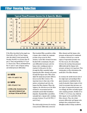
Typical Flow/Pressure Curves For A Specific Media
1.75 25
(PSI) Differential Pressure (Bar)
1.5 20
1.25
1. 15 200 SUS 100 SUS
0.75 10
0.5
0.25 5
0 0
0 10 20 30 40 50 60 70 80 90 100
(GPM) Flow (LPM)
0 25 50 75 100 125 150 200 225 250 275 300 325 350 375
If the filter described in the graph was Most standard filter assemblies utilize filter element and the bypass valve
fitted with a 50 psi (3.4 bar) bypass a bypass valve to limit the maximum pressure setting must be considered.
valve the initial (clean) pressure dif- pressure drop across the filter A cellulose element has a narrow
ferential should be no greater than 25 element. As the filter element becomes region of exponential pressure rise.
2
psi (1.7 bar) and preferably 16 ¼3 psi blocked with contaminant, the pres- For this reason, the relationship
(1.1 bar)or less. This is calculated from sure differential increases until the between the starting clean pressure
the 3:1 and 2:1 ratio of bypass setting bypass valve cracking pressure is differential and the bypass valve
and initial pressure differential. reached. At this point, the flow pressure setting is very important. This
through the filter assembly begins relationship in effect determines the
bypassing the filter element and passes useful life of the filter element.
3:1 RATIO through the bypass valve. This action
limits the maximum pressure differen- In contrast, the useful element life of
2
▼ 50/3 = 16 /3 psid (1.1 bar)
tial across the filter element. The the single layer and multilayer fiber-
important issue is that some of the glass elements is established by the
2:1 RATIO
system contaminant particles also nearly horizontal, linear region of rela-
▼ 50/2 = 25 psid (1.7 bar) bypass the filter element. When this tively low pressure drop increase, not
happens, the effectiveness of the filter the region of exponential pressure rise.
▼ At 200 sus fluid, the maximum flow element is compromised and the Accordingly, the filter assembly bypass
range would be between 42 gpm attainable system fluid cleanliness valve cracking pressure, whether 25 or
and 54 gpm (159 lpm and 204 lpm) degrades. Standard filter assemblies 75 PSI (1.7 or 5.2 bar), has relatively
normally have a bypass valve cracking little impact on the useful life of the
pressure between 25 and 100 PSI (1.7 filter element. Thus, the initial
and 6.9 bar). pressure differential and bypass valve
setting is less a sizing factor when
The relationship between the starting fiberglass media is being considered.
clean pressure differential across the
27