
Page 3 - Proportion-Air - MM1/MM2 Control Valves
P. 3
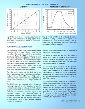
PERFORMANCE CHARACTERISTICS
 FEATURES                      LINEARITY                                      RESPONSE TO STEP INPUT


           Fig. 1 This chart shows linear characteristics of      Fig.  2  Times  for  MM  to  fi  ll/exhaust  a  closed
 APPLICATIONS  MM  products  when  given  a  ramp  signal  from   chamber.      Step      command        signal     is
           0-10 volts. Characteristics would be similar for       superimposed  over  pressure  trace.  Time  is
           4-20 mA units.                                         determined  by  difference  between  command
                                                                  signal and pressure achieved.
           FUNCTIONAL DESCRIPTION


           The MM series proportional control valves utilize   Closed loop proportional control of pressure is
           Proportion-Air’s  unique  closed  loop  control  maintained in this manner.
           technology  for  superior  control  of  pressurized
           gases  and  fluids.  The  MM  is  designed  to  have   The  MM2  is  similar  to  the  MM1  but  uses  a
           “Universal  Mounting”  capabilities  which  include    double  loop  control  scheme.  In  addition  to  the
           Din Rail, panel mount, or manifold mounting for        internal  pressure  transducer,  the  MM2  also
           use  on  sub-base  for  multiple  unit  applications.   receives a feedback signal (0-10 Vdc Standard)
           Sub-base configurations are available from 2-12        from an external sensing device.
           units. The sub-base offers a common supply and
           exhaust  port  with  individual  controlled  outlet    The  external  signal  functions  as  the  primary
           ports to minimize plumbing connections.                feedback  and  is  compared  to  the  command
                                                                  signal.  This  comparison  is  summed  with  the
           The  MM  series  units  can  be  built  as  single     internal pressure transducer signal. A difference
           closed loop or dual closed loop (cascading loop)       between the two comparisons causes one of the
           control  valves.  The  MM1  and  MM2  deliver          two solenoid valves to open allowing flow in or
           pressure control which is linearly proportional to     out of the system.
           either  a  DC  current  or  DC  voltage  command
           input.                                                 Since  the  secondary  feedback  is  an  electrical

           The  MM1  uses  two  solenoid  valves  to  control     signal, many types of sensors may be used as a
           system pressure. One valve functions as an inlet       feedback  such  as  force,  position,  pressure,
           control, the other as an exhaust control. A strain     vacuum, etc. An analog output is also standard
           gauge pressure transducer measures the system          on both the MM1 and MM2 to be used for data
           pressure and provides a feedback signal to the         acquisition  or  to  a  panel  meter  for  display.
           electronic  controls.  This  feedback  signal  is      The  analog  monitor  signal  is  taken  from  the
           compared  against  the  command  signal.  Any          internal pressure sensor on MM1‘s and from the
           difference  between  the  two  signals  causes  one    secondary feedback on the MM2.
           of the solenoid valves to open allowing pressure
           in or out of the system.                                                           317-335-2602 ▪ PROPORTION-AIR