
Page 7 - Proportion-Air - MM1/MM2 Control Valves
P. 7
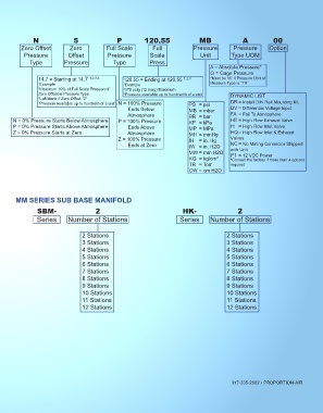
N                5                P          120.55                MB               A            00
          Zero Offset        Zero           Full Scale        Full             Pressure        Pressure      Option
           Pressure         Offset          Pressure         Scale               Unit         Type UOM
             Type          Pressure           Type           Press
                                                                                     A = Absolute Pressure*
                                                                                     G = Gage Pressure
                14.7 = Starting at 14.7  1,2,3,4   120.55 = Ending at 120.55  1,2,3  *Must be “A” if Pressure Unit of
 X = No Monitor Signal   1 Example                 1 Example                         Measure Type is “TR”
 Sinking
 C = 4 to 20 mADC  2 Maximum 10% of Full Scale Pressure if   2 175 psig (12 barg) Maximum
 E = 0 to 10 VDC  Zero Offset is Pressure Type     3 Pressure available up to hundredth of a unit  DYNAMIC LIST
                 Left blank if Zero Offset “Z”
                3
 K = 0 to 5 VDC 1  4 Pressure Available up to hundreth of a unit N = 100% Pressure  PS  = psi   DR = Install DIN Rail Mounting Kit
 Sourcing
 S = 4 to 20 mADC                                      Ends Below            MB  = mbar       DV = Differential Voltage Input
 V = 1 to 5 VDC 1                                      Atmosphere            BR  = bar        FA  =  Fail To Atmosphere
 1 Only available if the same Input  N = 0% Pressure Starts Below Atmosphere   P = 100% Pressure  HE = High Flow Exhaust Valve
 Signal Range is selected  P = 0% Pressure Starts Above Atmosphere          Ends Above  KP  = kPa     = High Flow Inlet Valve
                                                                             MP  = MPa
      Z = 0% Pressure Starts at Zero                   Atmosphere            MH  = mmHg       HQ = High Flow Inlet & Exhaust
                                                Z = 100% Pressure            IH  = in. Hg     Valves
                                                       Ends at Zero          IW  = in. H2O    NC = No Mating Connector Shipped
                                                                             MW = mm H2O      with Unit
                                                                                              P1 = 12 VDC Power
                                                                             KG  = kg/cm²     *Consult the factory if more than 4 options
                                                                             TR  = Torr       required
                                                                             CW = cm H2O


       MM SERIES SUB BASE MANIFOLD

                SBM-                   2                                  HK-                   2
                Series      Number of Stations                           Series      Number of Stations


                                  2 Stations                                                2 Stations
                                  3 Stations                                                3 Stations
                                  4 Stations                                                4 Stations
                                  5 Stations                                                5 Stations
                                  6 Stations                                                6 Stations
                                  7 Stations                                                7 Stations
                                  8 Stations                                                8 Stations
                                  9 Stations                                                9 Stations
                                  10 Stations                                               10 Stations
                                  11 Stations                                               11 Stations
                                  12 Stations                                               12 Stations


                                                                                              317-335-2602 ▪ PROPORTION-AIR