
Page 14 - Parker - Heavy Duty Hydraulic Cylinders
P. 14
Catalog HY08-1114-4/NA Heavy Duty Hydraulic Cylinders
Features and Benefits Series 2H
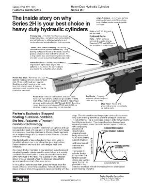
The inside story on why Align-A-Groove – A /16" wide surface
3
machined at each end of the cylinder
Series 2H is your best choice in body. Makes precise mounting quick
and easy.
heavy duty hydraulic cylinders
Ports – SAE “O” ring ports
are standard.
Primary Seal – TS-2000 Rod Seal is a proven Optional Ports
leakproof design – completely self-compensating Ports – NPTF ports are
and self-relieving to withstand variations and optional at no extra charge.
conform to mechanical deflection that may occur. Oversize NPTF and SAE ports
are available at extra charge.
“Jewel” Rod Gland Assembly – Externally
removable without cylinder disassembly. Long
bearing surface is inboard of the seals, assuring
positive lubrication from within the cylinder. An
o-ring is used as a seal between gland and head,
and also serves as a prevailing torque-type lock.
Secondary Seal – Double-Service
Wiperseal™ wipes clean any oil film
adhering to the rod on the extend stroke
and cleans the rod on the return stroke.
Piston Rod Stud – Furnished on 2.000"
diameter rods and smaller when standard
style #4 rod end threads are required.
Studs have rolled threads and are made
from high strength steel. Anaerobic
adhesive is used to permanently lock the
stud to the piston rod.
Piston Rod – Medium carbon steel, induction case- End Seals – Pressure-
hardened, hard chrome-plated and polished to 10 RMS actuated cylinder body-to-
finish. Piston rods are made from 85,000 to 100,000 psi head and cap o-rings.
minimum yield material in .625" through 4.000" diameters. Steel Head – Bored and
Larger diameters vary between 57,000 and 90,000 psi grooved to provide concentricity
minimum material, depending on rod diameter. for mating parts.
Parker’s Exclusive Stepped
floating cushions combine steps. The deceleration cushion plunger curves shape comes
very close to being theoretical, with the exception of the last
the best features of known 1 flexibility in application. The stepped cushion design shows
/2 inch of travel. This is a constant shape in order to have some
cushion technology. reduced pressure peaks for most load and speed conditions,
Deceleration devices or built-in “cushions” are optional and can with comparable
reduction of
be supplied at head end, cap end, or both ends without change objectionable
in envelope or mounting dimensions. Parker cylinder cushions stopping forces
are a stepped design and combine the best features of known being transmitted
cushion technology. to the load and the
Standard straight or tapered cushions have been used in support structure.
industrial cylinders over a very broad range of applications. All Parker Hannifin
Parker research has found that both designs have their cushions are
limitations. adjustable.
As a result, Parker has taken a new approach in cushioning of The Series 2H
industrial hydraulic cylinders and for specific load and velocity cylinder design
conditions have been able to obtain deceleration curves that incorporates the
come very close to the ideal. The success lies in a stepped longest cushion
sleeve or spear concept where the steps are calculated to sleeve and cushion
approximate theoretical orifice area curves. spear that can be
In the cushion performance chart, pressure traces show the provided in the
results of typical orifice flow conditions. Tests of a three-step standard envelope without decreasing the rod bearing and
sleeve or spear show three pressure pulses coinciding with the piston bearing strengths.
4 Parker Hannifin Corporation
Industrial Cylinder Division
www.parker.com/cylinder Des Plaines, Illinois USA