
Page 18 - Parker - Heavy Duty Hydraulic Cylinders
P. 18
Catalog HY08-1114-4/NA Heavy Duty Hydraulic Cylinders
2H Model Code / How To Order Series 2H
2H Model Code
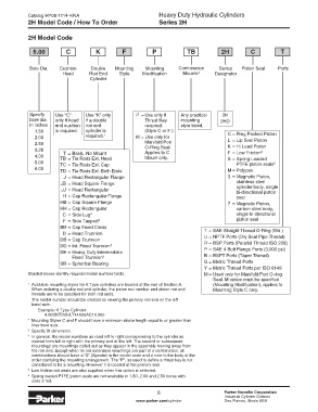
5.00 C K F P TB 2H C T
Bore Dia. Cushion Double Mounting Mounting Combination Series Piston Seal Ports
Head Rod End Style Modification Mounts 4 Designator
Cylinder
Specify Use “C” Use “K” only P = Use only if Any practical 2H
bore dia. only if head if a double Thrust Key mounting 2HD
in inches end cushion rod end required. style listed.
1.50 is required. cylinder is (Style C or F.) C = Ring Packed Piston
2.00 required. 1 M = Use only for L = Lip Seal Piston
2.50 Manifold Port K = Hi Load Piston
3.25 T = Basic, No Mount O-Ring Seal. F = Low Friction 5
Applies to C
4.00 TB = Tie Rods Ext. Head Mount only. S = Spring Loaded
5.00 TC = Tie Rods Ext. Cap PTFE piston seals
6
6.00
TD = Tie Rods Ext. Both Ends M = Polypak
J = Head Rectangular Flange 3 = Magnetic Piston,
JB = Head Square Flange stainless steel
JJ = Head Rectangular cylinder body, single
bi-directional piston
H = Cap Rectangular Flange seal
HB = Cap Square Flange 7 = Magnetic Piston,
HH = Cap Rectangular carbon steel body,
C = Side Lug 2 single bi-directional
F = Side Tapped 2 piston seal
BB = Cap Fixed Clevis
D = Head Trunnion T = SAE Straight Thread O-Ring (Std.)
DB = Cap Trunnion U = NPTF Ports (Dry Seal Pipe Thread)
DD = Int. Fixed Trunnion 3 R = BSP Ports (Parallel Thread ISO 228)
DE = Heavy Duty Intermediate P = SAE 4-Bolt Flange Ports (3,000 psi)
Fixed Trunnion 3 B = BSPT Ports (Taper Thread)
SB = Spherical Bearing G = Metric Thread Ports
Y = Metric Thread Ports per ISO 6149
Shaded boxes identify required model number fields. M = Used only for Manifold Port O-ring
Seal. M option must be specified
1 Available mounting styles for K Type cylinders are located at the end of Section A. (Mounting Modification), applies to
When ordering a double rod end cylinder, the piston rod number and piston rod end Mounting Style C only.
threads are to be specified for both rod ends.
The model number should be created as viewing the primary rod end on the left
hand side.
Example: K Type Cylinder:
4.00CKTD2HLT14A28AC10.000
2 Mounting Styles C and F should have a minimum stroke length equal to or greater than
their bore size.
3 Specify XI dimension.
4 In general, the model numbers as read left to right corresponding to the cylinder as
viewed from left to right with the primary end at the left. The second or subsequent
mountings are mountings called out as they appear in the assembly moving away from
the rod end. Except when tie rod extension mountings are part of a combination, all
combinations should have a “S” (Special) in the model code and a note in the body of the
order clarifying the mounting arrangement. The “P”, as used to define a thrust key is not
considered to be a mounting. However it is located at the primary end.
5 Low friction rod seals are also supplied when this option is selected.
6 Spring loaded PTFE piston seals are not available in 1.50, 2.00 and 2.50 bores with
code 2 rod.
8 Parker Hannifin Corporation
Industrial Cylinder Division
www.parker.com/cylinder Des Plaines, Illinois USA