
Page 19 - Parker - Heavy Duty Hydraulic Cylinders
P. 19
Catalog HY08-1114-4/NA Heavy Duty Hydraulic Cylinders
2H Model Code / How To Order Series 2H
2H Model Code
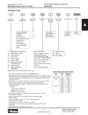
J S 1 4 2 A C 16.000
Common Special Piston Rod Piston Rod Piston Rod Piston Rod Cushion Cap Stroke 10
Modification 7 Modification Number 11 End Alternate Threads
Thread 14
A
Use only if special 1 Use only for Used only Specify
modifications are 2 male thread two if cushion in inches
required: 3 times longer required
Oversize Ports 4 than standard.
Port Position Change
Special Seals
10
Stop Tube
Stroke Adjusters
Tie Rod Supports
Other
J = High Water Content Fluid Style 4 Small Male A = UNF Standard
V = Fluorocarbon Seals Style 7 Female Thread for M = Metric 15
W = Water Service Spherical Rod Eye for N = No Thread 16
X = EPR Seals Piston Rod Codes Larger
2 = Class 2 Seals than Code #1 (Style SB only)
4 = Class 4 Seals Style 8 Intermediate Male
12
E = Fluorocarbon Seals – Style 9 Short Female
Piston Rod only Style 55 Rod End for Flange
H = Class 8 Seals 8 Coupling
N = High Temperature Style 3 Special (Specify) 13
Rod Gland 9
Shaded boxes identify required model number fields.
Style 9 Minimum Stroke Table
7 See common modifications Section D for additional options. Bore Rod Minimum
8 Class 8 piston seals will be cast iron rings (Piston Code C) in 1.50, 2.00 & 2.50 inch Ø Ø Stroke
bores with code 2 rod. Spring loaded PTFE piston seals are not available in these
bore and rod combinations. In all other bore and rod combinations, Piston Code S 1.50 - 4.00 All None
should be specified. 5.00 2.000 None
9 Energized PTFE rod seals & wiperseal. All other cylinder seals are fluorocarbon. 2.500 1.000
10 S = Stop Tube. Specify: stop tube length, net stroke and gross stroke. 3.000 1.375
Gross stroke = stop tube length + net stroke. Gross stroke to be placed in the
model number field. 3.500 1.625
Example: 6.00 2.500 None
2.000 inches long stop tube 3.000 1.375
+14.000 inches net stroke 3.500 1.375
16.000 inches gross stroke 4.000 2.000
11 Refer to Rod buckling chart in Section E to assure rod number selected
will not buckle under load.
12 Style 9 stroke restrictions may apply. See Style 9 Minimum Stroke
Table for details.
13 Provide dimensions for KK, A, W or WF. If otherwise special,
furnish dimensioned sketch.
14 Available only in combination with Style 4 or Style 8.
15 See Section D for detailed information regarding standard metric rod end
thread sizes.
16 Must be specified for Piston Rod End Style 55.
9 Parker Hannifin Corporation
Industrial Cylinder Division
www.parker.com/cylinder Des Plaines, Illinois USA