
Page 7 - Linde - VT Modular, Modular system for LSC manifold valve plates
P. 7
Model Code Breakdown.
Model code character 12 – Valve Actuation Type
Valve spools can be hydraulically piloted by ports on the valve end
caps, or electrically piloted by proportional solenoid valves moun-
ted on the base block or expansion modules. When two electrically
piloted valves are mounted on the same module, the pilot valves are
“stacked”. The inner pilot valves control the upper main valve, and
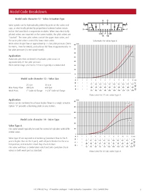
the outer pilot valves control the lower main valve. Schematic for valve type A
Main valves begin flow at approximately 7.5 bar pilot pressure (3mm
for VW25, 2mm for VW30), and achieve full flow at approximately 19
bar pilot pressure (12 mm spool travel).
Application
Automatic pilot line air bleed for hydraulic pilot occurs at
approximately 21 bar pilot pressure.
Pilot control range of 6 bar to 21 bar is typically recommended.
Model code character 13 – Valve Size
25 size 30 size
Max Pump Flow 400 lpm 600 lpm
Work Ports 1” Code 62 flange 1-1/4” Code 62 flange
Flow curve for 25 size valve type A
Application
Valves can be combined to achieve higher flows to a single actuator.
Option “0” provides a blanking plate on any station.
Model code character 14 – Valve Type
Valve Type A
This valve would typically be used for control of cylinders with diffe-
rential areas.
Valve type A has asymmetrical metering (maximum flow to the A
port is higher than to the B port), with all ports blocked in the neu-
tral position, and includes a load drop check feature.
This valve will have a combination relief and anti-cavitation check
valves in both work port as standard. Flow curve for 30 size valve type A
7