
Page 12 - Parker - K220LS Mobile directional control valve
P. 12
Catalogue HY17-8537/UK Mobile Directional Control Valve
Inlet section K220LS
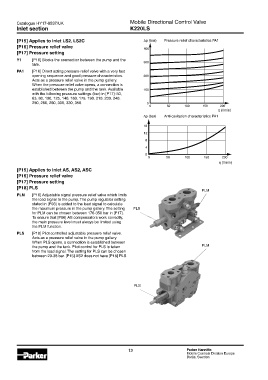
[P15] Applies to inlet LS2, LS2C Δp (bar) Pressure relief characteristics PA1
[P16] Pressure relief valve 400
[P17] Pressure setting
Y1 [P16] Blocks the connection between the pump and the 300
tank.
PA1 [P16] Direct acting pressure relief valve with a very fast
opening sequence and good pressure characteristics. 200
Acts as a pressure relief valve in the pump gallery.
When the pressure relief valve opens, a connection is
established between the pump and the tank. Available 100
with the following pressure settings (bar) in [P17]: 50,
63, 80, 100, 125, 140, 160, 175, 190, 210, 230, 240,
250, 260, 280, 300, 330, 350. 0
0 50 100 150 200
q (l/min)
Δp (bar) Anti-cavitation characteristics PA1
16
12
8
4
0
0 50 100 150 200
q (l/min)
[P15] Applies to inlet AS, AS2, ASC
[P16] Pressure relief valve
[P17] Pressure setting
[P18] PLS
PLM
PLM [P16] Adjustable signal pressure relief valve which limits
the load signal to the pump. The pump regulator setting
stated in [P03] is added to the load signal to calculate
the maximum pressure in the pump gallery. The setting PLS
for PLM can be chosen between 176-350 bar in [P17].
To ensure that [P66] AS compensators work correctly,
the main pressure level must always be limited using
the PLM function.
PLS [P18] Pilot controlled adjustable pressure relief valve.
Acts as a pressure relief valve in the pump gallery.
When PLS opens, a connection is established between
the pump and the tank. Pilot control for PLS is taken PLM
from the load signal. The setting for PLS can be chosen
between 20-38 bar. [P15] AS2 does not have [P18] PLS.
PLS
12 Parker Hannifin
Mobile Controls Division Europe
Borås, Sweden