
Page 14 - Parker - K220LS Mobile directional control valve
P. 14
Catalogue HY17-8537/UK Mobile Directional Control Valve
Inlet section K220LS
[P24] Tank connection T2
Can either be used as a tank connection or fitted with a counter
pressure valve.
The counter pressure valve increases the pressure in the valve's
tank gallery. By raising the counter pressure, the anti-cavitation
characteristics of the K220LS are improved still further. Good
make-up characteristics eliminate the risk of cavitation and
reduce the risk of damage to the cylinder seals. They are also
important for functions in which a lowering movement changes
to a lifting movement without a time delay. For example, when an
implement is lowered and then pressed down into the ground, or
when a machine turns on sloping ground.
T2 Tank connection T2 open.
T2B Tank connection T2 plugged.
MF5 Counter pressure valve preset to give 5 bar counter
pressure at a flow of 20 l/min.
MF9 Counter pressure valve preset to give 9 bar counter
pressure at a flow of 20 l/min.
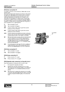
Connection:
A055 Counter pressure valve preset to give 5 bar counter pres-
sure at a flow of 20 l/min. Also has built-in leakage for the MP
counter pressure when no work section is activated.
MP Pilot operated counter pressure valve for external control
of counter pressure from 0 to 36 bar. Only provides a
counter pressure on receipt of a signal. The maximum
permitted signal is 30 bar. The relationship between
counter pressure and signal is 1.2:1. Connection thread
G1/4 or 9/16-18 UNF-2B.
MP5 As counter pressure valve type MP with the addition of
a spring providing 5 bar counter pressure at a flow of
20 l/min. Connection thread G1/4 or 9/16-18 UNF-2B.
[P25] Tank connection T1
T1 Tank connection T1 is open.
T1B Tank connection T1 is plugged.
[P26] Pump connection P1
P1 Pump connection P1 is open.
P1B Pump connection P1 is plugged.
[P28] Separate tank connection for the pilot circuit
Note: Only possible with inlet section [P15] LS2C or ASC.
/ Not prepared for separate pilot return.
TP Separate tank connection for the pilot circuit is open.
The connection to the main tank gallery of the directional
valve is blocked. For more details see [P40] in the end
section.
TPB The end section is prepared for separate tank connection
of the pilot circuit and plugged. The tank return of the pilot
circuit is connected to the tank gallery of the directional
valve.
14 Parker Hannifin
Mobile Controls Division Europe
Borås, Sweden