
Page 21 - Parker - K220LS Mobile directional control valve
P. 21
Catalogue HY17-8537/UK Mobile Directional Control Valve
Work section K220LS
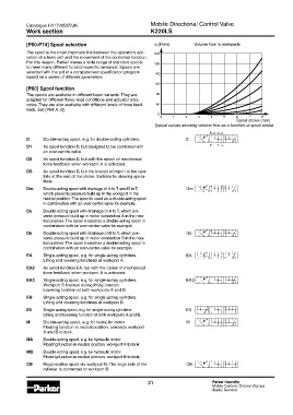
[P60-P74] Spool selection q (l/min) Volume flow in workports
The spool is the most important link between the operator’s acti- 240
vation of a lever unit and the movement of the controlled function.
For this reason, Parker makes a wide range of standard spools 200
to meet many different function-specific demands. Spools are
selected with the aid of a computerised specification program 160
based on a series of different parameters.
120
[P60] Spool function
The spools are available in different basic variants. They are 80
adapted for different flows, load conditions and actuator area
ratios. They are also available with different levels of force feed- 40
back, see [P64 A, B].
0
0 1 2 3 4 5 6 7 8
Spool stroke (mm)
Typical curves showing volume flow as a function of spool stroke.
D Double-acting spool, e.g. for double-acting cylinders.
D1 As spool function D, but designed to be combined with
an over-centre valve.
D2 As spool function D, but with the option of mechanical
force feedback when workport A is activated.
DS As spool function D, but the braced workport to the tank
falls at the end of the stroke. Suitable for slewing opera-
tions.
Dm Double-acting spool with drainage of A to T and B to T,
which prevents pressure build up in the workport in the
neutral position. The spool is used as a double-acting spool
in combination with an over-centre valve for example.
Da Double-acting spool with drainage of A to T, which pre-
vents pressure build up in motor connection A in the neu-
tral position. The spool is used as a double-acting spool in
combination with an over-centre valve for example.
Db Double-acting spool with drainage of B to T, which pre-
vents pressure build up in motor connection B in the neu-
tral position. The spool is used as a double-acting spool in
combination with an over-centre valve for example.
EA Single-acting spool, e.g. for single-acting cylinders.
Lifting and lowering functions at workport A.
EA2 As spool function EA, but with the option of mechanical
force feedback when workport A is activated.
EA3 Single-acting spool, e.g. for single-acting cylinders.
Workport B blocked during lifting function.
Lowering function at both workports A and B.
EB Single-acting spool, e.g. for single-acting cylinders.
Lifting and lowering functions at workport B.
E5 Single-acting spool, e.g. for single-acting cylinders.
Lifting and lowering function at both workports A and B.
M Double-acting spool, e.g. for hydraulic motor.
Floating function in neutral position, connects workport
A and B to tank.
MA Double-acting spool, e.g. for hydraulic motor.
Floating function in neutral position, workport A to tank.
MB Double-acting spool, e.g. for hydraulic motor.
Floating function in neutral position, workport B to tank.
CB Regenerative spool via workport B. The large side of the
cylinder is connected to workport B.
21 Parker Hannifin
Mobile Controls Division Europe
Borås, Sweden