
Page 24 - Parker - K220LS Mobile directional control valve
P. 24
Catalogue HY17-8537/UK Mobile Directional Control Valve
Work section K220LS
[P69] Spool designation
Spool selection is carried out using the configuration program for
K220LS.
[P72] Flow settings
With PC spool actuators, flow limitation over the spool to workports
A and B can be effected by means of mechanical limitation of the
spool stroke length. By choosing options in [P59], mechanical
stroke limitation can be combined with EC2 and ECS2.
/ No flow settings.
Qset Limitation of maximum flow in workports A and B.
Qset A Limitation of maximum flow in workport A.
Qset B Limitation of maximum flow in workport B.
[P72A] Desired set flow
The desired flow for workport A is entered here.
[P72B] Desired set flow
The desired flow for workport B is entered here.
[P74] Variant for work section
/ No variant.
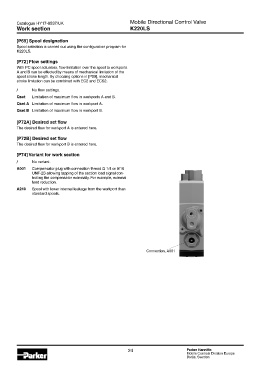
A001 Compensator plug with connection thread G 1/4 or 9/16
UNF-2B allowing tapping of the section load signal con-
trolling the compensator externally. For example, external
feed reduction.
A240 Spool with lower internal leakage from the workport than
standard spools.
Connection, A001
24 Parker Hannifin
Mobile Controls Division Europe
Borås, Sweden