
Page 26 - Parker - K220LS Mobile directional control valve
P. 26
Catalogue HY17-8537/UK Mobile Directional Control Valve
Work section K220LS
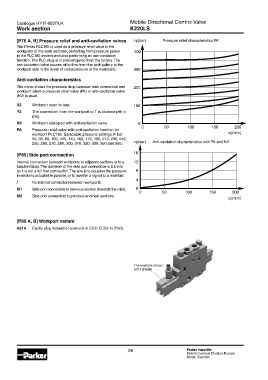
[P76 A, B] Pressure relief and anti-cavitation valves Δp(bar) Pressure relief characteristics PA
The Parker PLC185 is used as a pressure relief valve in the
workports of the work sections, protecting from pressure peaks 400
in the PLC185 system and also performing an anti-cavitation
function. The PLC plug-in is preconfigured from the factory. The
anti-cavitation valve causes oil to flow from the tank gallery to the
workport side in the event of underpressure in the workports. 300
Anti-cavitation characteristics
The curve shows the pressure drop between tank connection and 200
workport when a pressure relief valve (PA) or anti-cavitation valve
(N2) is used.
X2 Workport open to tank. 100
Y2 The connection from the workport to T is blocked with a
plug.
N2 Workport equipped with anti-cavitation valve. 0
0 50 100 150 200
PA Pressure relief valve with anti-cavitation function for
workport PLC185. Selectable pressure settings in bar: q(l/min)
50, 63, 80, 100, 125, 140, 160, 175, 190, 210, 230, 240,
250, 260, 270, 280, 300, 310, 320, 330, 350 and 365. Δp(bar) Anti-cavitation characteristics with PA and N2
[P85] Side port connection 16
Internal connection between workports to adjacent sections or to a 12
function block. The diameter of the side port connection is 8.5 mm
so it is not a full flow connection. The aim is to equalise the pressure 8
in sections actuated in parallel, or to transfer a signal to a manifold.
4
/ No internal connection between workports.
M1 Side port connection to previous section (towards the inlet). 0
0 50 100 150 200
M2 Side port connection to previous and next sections.
q(l/min)
[P89 A, B] Workport variant
A214 Cavity plug instead of solenoid in EC2/ ECS2 in [P50].
The example shows:
A214 [P89B]
26 Parker Hannifin
Mobile Controls Division Europe
Borås, Sweden