Page 311 - Parker - Parker Pneumatic
P. 311

PDE2600PNUK
            Parker Pneumatic                                         Origa OSP-E Electric Linear Actuators


           Loads, Forces and Moments


           Combined loads                           Equation of Combined Loads
           If the actuator is subjected to several forces,
           loads and moments at the same time,
           the maximum load is calculated with the            Fy        Fz       Mx      My       Mz


           equation shown here.                                     +          +           +                 +                   ≤1
           The maximum permissible loads must not          Fy (max)         Fz (max)     Mx (max)   My (max)     Mz (max)


           be exceeded.                             The total of the loads must not exceed  >1 under any circumstances.

                                                    M = F · l [Nm]        The distance (l , l , l ) for calculation of
                                                                                       z
                                                                                     y
                                                                                    x
                                                    M  = M x static  + M x dynamic  moments relates to the centre axis of the
                                                     x
                                                    M  = M y static  + M y dynamic  actuator. Bending moments are calculated
                                                     y
                                                    M  = M    + M         from the centre of the actuator and F
                                                     z   z static  z dynamic  indicates actual force.

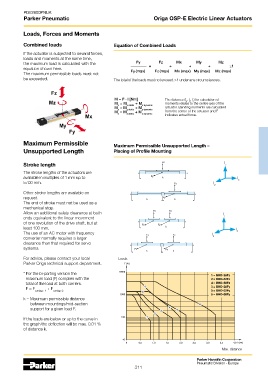
           Maximum Permissible                     Maximum Permissible Unsupported Length –
           Unsupported Length                      Placing of Profile Mounting


           Stroke length                                                                             l z
           The stroke lengths of the actuators are
           available in multiples of 1 mm up to                                                           l x
           5700 mm.                                                                             l
                                                                                                y
           Other stroke lengths are available on
           request.
           The end of stroke must not be used as a
           mechanical stop.
           Allow an additional safety clearance at both                                             l
           ends equivalent to the linear movement                                                   z
           of one revolution of the drive shaft, but at
           least 100 mm.                                                                                  l
           The use of an AC motor with frequency                                               l          x
           converter normally requires a larger                                                 y
           clearance than that required for servo
           systems.

           For advice, please contact your local      Loads
           Parker Origa technical support department.

           * For the bi-parting version the                                               1 = BHD-25Fz
             maximum load (F) complies with the                                                2 = BHD-32Fz
             total of the load at both carriers.                                               4 = BHD-50Fz
                       + F
             F = F carriage  1  carriage 2                                                    3 = BHD-25Fy
                                                                                               5 = BHD-32Fy
                                                                                          6 = BHD-50Fy
           k = Maximum permissible distance
               between mountings/mid-section
               support for a given load F.


           If the loads are below or up to the curve in
           the graph the deflection will be max. 0.01 %
           of distance k.


                                                                                                    Max. distance

                                                                                        Parker Hannifin Corporation
                                                                                        Pneumatic Division - Europe
                                                             311
   306   307   308   309   310   311   312   313   314   315   316